
Fully automatic logistics packaging robot

A fully automatic and robotic technology, applied in the mechanical field of packaging objects or materials, can solve the problems of low packaging efficiency of candies, achieve the effects of improving packaging efficiency, strengthening the limit effect, and reducing labor intensity

Active Publication Date: 2019-10-08
厦门狄耐克物联智慧科技有限公司
View PDF7 Cites 0 Cited by
  • Summary
  • Abstract
  • Description
  • Claims
  • Application Information

AI Technical Summary

Problems solved by technology

[0003] The present invention intends to provide a fully automatic material packaging robot to solve the current problem of low efficiency in candy packaging

Method used


Image

  • Fully automatic logistics packaging robot
  • Fully automatic logistics packaging robot

Examples


Embodiment 1

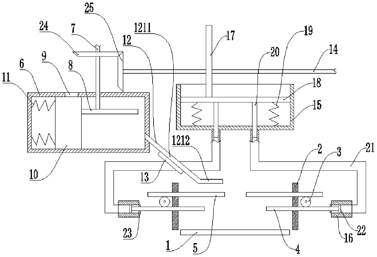
[0025] Basic as attached figure 1 Shown: a fully automatic logistics packaging robot, including a base on which a conveyor belt 1, a quantitative feeding mechanism and a packaging mechanism are installed, and the quantitative feeding mechanism is set toward the direction of the conveyor belt 1; the conveyor belt 1 in this embodiment is a belt commonly used in the market type conveyor, so I won’t go into details.

[0026] The quantitative feeding mechanism comprises a motor and a material box 6 welded on the support, the output shaft of the motor is welded with a vertical shaft 7 passing through the material box 6, and the vertical shaft 7 is sleeved with a cam-8; the material box 6 There is a feed inlet 9 on the top, and a slide block 10 is slidably connected to the cam-8 in the material box 6, and a spring-11 is fixedly connected between the slide block 10 and the material box 6, and the feed port 9 is located on the slide block 10. The bottom of the material box 6 is connec...

Embodiment 2

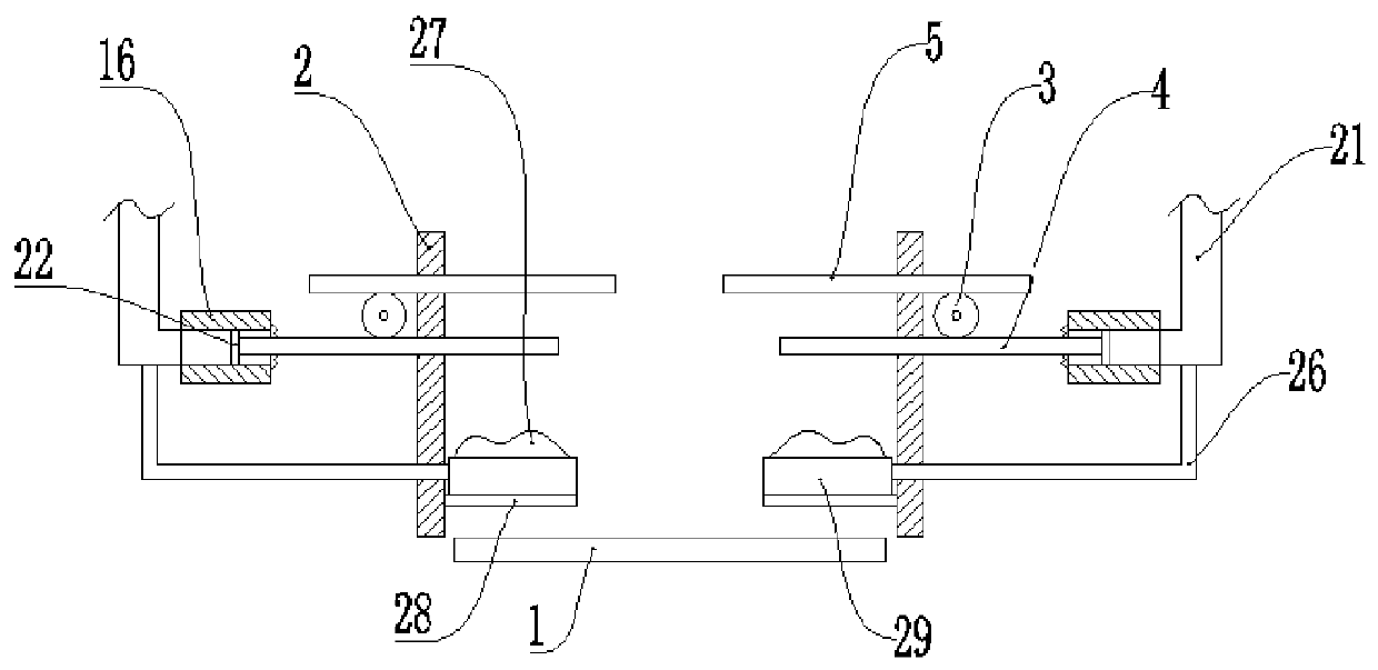
[0036] Basic as attached figure 2 As shown, the structure and implementation of Embodiment 2 are basically the same as Embodiment 1, the difference is that: the side pipe 26 passing through the fixing plate 2 is connected to the pipe 21, and the end of the side pipe 26 away from the pipe 21 is fixedly connected There is an air bag 27; the diameter of the side pipe 26 is smaller than that of the pipe 21. A side plate 28 is welded to the side of the fixed plate 2 close to the conveyor belt, and the side plate 28 is located below the airbag 27 ; a baffle plate 29 is welded on the side plate 28 .

[0037] The specific implementation process is as follows:

[0038] In use, when the lifting plate 18 moves downward, the vertical block 20 also moves downward; the vertical block 20 moves downward in the pipe 21, so that a part of the gas in the pipe 21 enters the cylinder 16, and another part of the gas enters the side In the pipe 26; because the diameter of the side pipe 26 is smal...


PUM


Abstract

The invention relates to the technical field of machinery for packaging articles or materials, and discloses a fully automatic logistics packaging robot, comprising a base, wherein a conveyor belt, aquantitative feeding mechanism and a packaging mechanism are arranged on the base, and the quantitative feeding mechanism is arranged toward the conveyor belt; the packaging mechanism comprises a reciprocator, fixing plates on both sides of the conveyor belt and gears rotatably connected to both sides of the conveyor belt, and the distance between the two gears is greater than the distance betweenthe two fixing plates; the upper and lower sides of the two gears are provided with a rack 1 and a rack 2 which are meshed with the gears, and the rack 1 and the rack 2 are slidably connected with the fixing plates; the reciprocator drives the rack 1 to reciprocate in the horizontal direction. This fully automatic logistics packaging robot mainly solves the problem that the current candy packaging efficiency is low.

Description

technical field [0001] The invention relates to the technical field of machinery for packaging objects or materials. Background technique [0002] Candies need to be packaged before they are sold. The packaging box for packaging candy is usually made of paper, and the width of the packaging box gradually increases from top to bottom. There is an adhesive layer on the inner wall of the top side of the packaging box; currently, some small The candy processing factory mainly uses the staff to pick up the candies into the packaging box, and then stick the two side walls of the top of the packaging box together, and realize the sealing of the packaging box through the adhesive layer; the candies are packaged in the above-mentioned way. On the one hand, the labor intensity is high, on the other hand, the packaging efficiency is low. Contents of the invention [0003] The present invention intends to provide a fully automatic material packing robot to solve the current problem o...

Claims


Application Information

Patent Timeline
Patent Type & Authority Applications(China)
IPC IPC(8): B65B43/54B65B7/20B65B25/00
CPCB65B7/20B65B25/005B65B43/54
Inventor 林礼区
Owner 厦门狄耐克物联智慧科技有限公司
Learn More