
Reinforced propeller for unmanned aerial vehicle

An enhanced propeller technology, applied in the field of drones, can solve the problems of low service life of propeller blades, easy breakage of propeller blades, economic losses, etc., and achieve the effect of reducing capital expenditure, reducing experiment cost and reducing waste

Inactive Publication Date: 2019-10-08
智飞智能装备科技东台有限公司
View PDF5 Cites 1 Cited by
  • Summary
  • Abstract
  • Description
  • Claims
  • Application Information

AI Technical Summary

Problems solved by technology

[0002] UAVs use electric motors to drive the propellers. The rotation of the propeller blades will cause friction with the air. The longer the time, the lower the service life of the propeller blades. Moreover, a new drone requires a lot of experiments before mass production. To be able to be officially produced, the size of the propeller blade and its extension length require a lot of testing. The existing experimental method is to install propeller blades of different sizes for trial operation. This method requires a large amount of funds and is more efficient. Slow, and ordinary propeller blades are easy to break, causing financial loss

Method used


Image

  • Reinforced propeller for unmanned aerial vehicle
  • Reinforced propeller for unmanned aerial vehicle
  • Reinforced propeller for unmanned aerial vehicle

Examples


Embodiment Construction

[0025] The technical solutions in the embodiments of the present invention will be clearly and completely described below in conjunction with the accompanying drawings in the embodiments of the present invention. Obviously, the described embodiments are only a part of the embodiments of the present invention, rather than all the embodiments. Based on the embodiments of the present invention, all other embodiments obtained by those of ordinary skill in the art without creative work shall fall within the protection scope of the present invention.

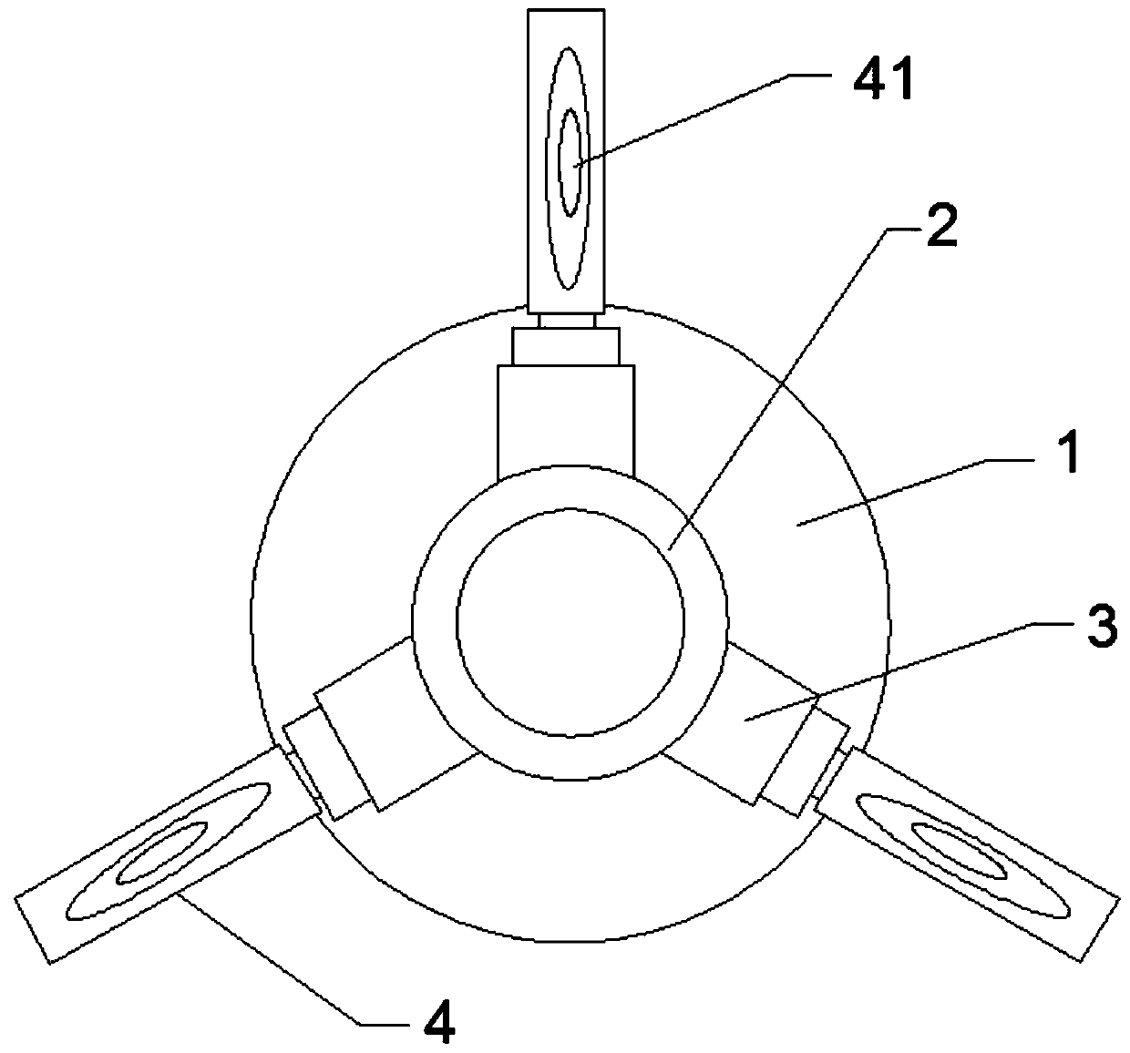
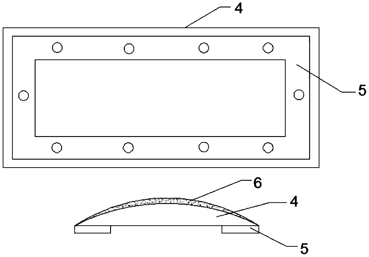
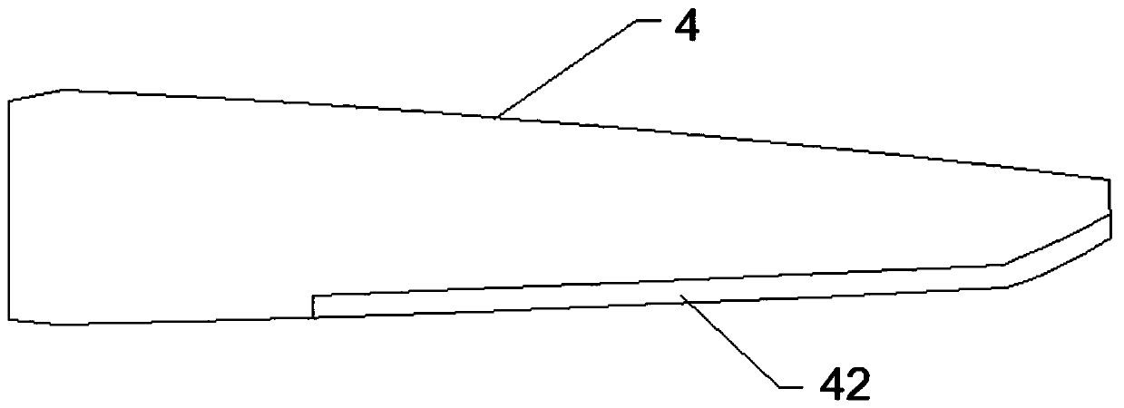
[0026] See Figure 1-Figure 4 A reinforced propeller for unmanned aerial vehicles shown includes an unmanned aerial vehicle motor 1, a connecting hoop 2 is provided on the top of a rotating shaft of the unmanned aerial vehicle motor 1, and a side surface of the connecting hoop 2 is arranged A telescopic rod 3, the left end of the telescopic rod 3 is fixedly connected to the side surface of the connecting hoop 2, a propeller blade 4 is pr...


PUM


Abstract

The invention discloses a reinforced propeller for an unmanned aerial vehicle. The reinforced propeller comprises an unmanned aerial vehicle motor, wherein a connecting hoop is arranged at the top endof a rotating shaft at the top of the unmanned aerial vehicle motor, a telescopic rod is arranged on the side surface of the connecting hoop, the left end of the telescopic rod is fixedly connected with the side surface of the connecting hoop, propeller blades are arranged on the top surface of the right end of the telescopic rod, vortex coils are arranged on the upper surfaces of the propeller blades, electromagnetic coils parallel to the vortex coils are arranged on the lower surface of the propeller blades, the input ends of the electromagnetic coils are connected with a transformer, the transformer is connected with a micro control computer, metal covered edges are covered on the front edges of the propeller blades and close to the outer sides, the metal covered edges are made of aluminum alloy materials, and the metal covered edges and the propeller blades are integrally formed. According to the reinforced propeller, the service life of the propeller can be prolonged, the rotating radius of the propeller blades can be adjusted by the telescopic rod, so that the flying condition of the unmanned aerial vehicle can be effectively adjusted; and meanwhile, the propeller can be automatically heated and deiced continuously when the unmanned aerial vehicle flies.

Description

Technical field [0001] The invention relates to the technical field of unmanned aerial vehicles, in particular to a reinforced propeller for unmanned aerial vehicles. Background technique [0002] UAVs use electric motors to drive the propellers. The rotation of the propeller blades will create friction with the air. The longer the time, the lower the service life of the propeller blades. Moreover, a lot of experiments are required before mass production of a new UAV. To be able to formally produce, the size of the propeller blade and its extension length require a lot of testing. The existing experimental method is to install propeller blades of different sizes for trial operation. This method requires more capital and is more efficient. Slow, and ordinary propeller blades are easily broken, causing economic losses. Summary of the invention [0003] The object of the present invention is to provide a reinforced propeller for unmanned aerial vehicles to solve the problems raised ...

Claims


Application Information

Patent Timeline
Patent Type & Authority Applications(China)
IPC IPC(8): B64C27/473B64D15/12B64D15/20
CPCB64C27/473B64D15/12B64D15/20B64U10/10
Inventor 吴国寿
Owner 智飞智能装备科技东台有限公司
Learn More