A microfluidic device and method for sorting droplets based on the principle of dielectrophoresis
A microfluidic device and a technology of dielectrophoresis, which are applied in the field of microfluidics, can solve the problems of inaccurate droplet sorting, and achieve the effects of simple structure and volume reduction.
- Summary
- Abstract
- Description
- Claims
- Application Information
AI Technical Summary
Problems solved by technology
Method used
Image
Examples
Embodiment 1
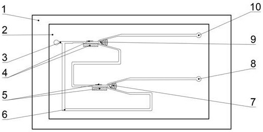
[0035] Embodiment 1: as figure 1As shown, a microfluidic device for sorting droplets based on the principle of dielectrophoresis, including a glass substrate 1 and a PDMS chip 2 fixed thereon, the PDMS chip 2 is provided with a primary sorter 9 and a secondary The first-stage sorter 7, the first-stage sorter 9 and the second-stage sorter 7 have the same structure, both of which are composed of a transverse channel that can pass through a single droplet and two branch channels that are connected to the transverse channel. A sorting structure and a balance pressure auxiliary structure are provided between the branch channels, a first electric field 4 is provided on the transverse channel of the primary separator 9, a second electric field 5 is provided on the transverse channel of the secondary separator 7, and a second electric field 5 is provided on the transverse channel of the secondary separator 7. Both the first electric field 4 and the second electric field 5 are composed...
Embodiment 2
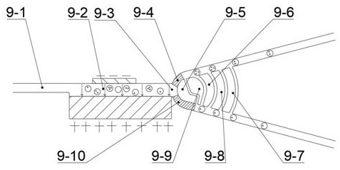
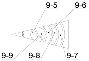
[0039] Embodiment 2: In this embodiment, the structure of the first-level sorter 9 and the second-level sorter 7 is described in detail. Because the two structures are the same, the first-level sorter 9 is used for illustration here, specifically as Figure 2-3 As shown, the first-stage sorter 9 includes a lateral channel composed of a limiting channel 9-1 and an electric field microchannel 9-2, a split inlet 9-3, a first sorting structure 9-5, and a second sub-structure 9-9. The sorting structure, the balance pressure auxiliary structure composed of the first auxiliary structure 9-6, the second auxiliary structure 9-7 and the third auxiliary structure 9-8.
[0040] One end of the limiting channel 9-1 is connected to the inlet 3, and the other end is connected to the electric field microchannel 9-2. The limiting channel 9-1 mainly allows liquid droplets to pass through individually. The upper pole plate and the lower pole plate of the electric field 4, the end of the electric ...
Embodiment 3
[0047] Embodiment 3: In this example, the specific dimensions of each part are limited, wherein the PDMS chip 2 is 120mm long, 60mm wide, and 10mm high, and the angle between the two branch channels of the primary sorter 9 is 30° ,like image 3 shown. The width of the limiting passage 9-1 is 0.025mm, the height is 0.025mm, and the length is 3mm; the length of the first sub-channel 9-4 is 0.050mm, and the width is 0.025mm; the length of the second sub-channel 9-10 is 0.100mm, the width is 0.025mm; the width of the microchannel between the first sorting structure 9-5 and the second sorting structure 9-9 is 0.010mm, the first auxiliary structure 9-6, the second auxiliary structure 9 The distance between -7 and the third auxiliary structure 9-8 is 0.015mm, and the widths of the three auxiliary structures are all 0.045mm. Other connecting channels have a width of 0.050mm and a height of 0.050mm.
PUM
 Abstract
Description
Claims
Application Information
 - R&D Engineer
- R&D Manager
- IP Professional
- Industry Leading Data Capabilities
- Powerful AI technology
- Patent DNA Extraction
Browse by: Latest US Patents, China's latest patents, Technical Efficacy Thesaurus, Application Domain, Technology Topic, Popular Technical Reports.
© 2024 PatSnap. All rights reserved.Legal|Privacy policy|Modern Slavery Act Transparency Statement|Sitemap|About US| Contact US: help@patsnap.com


