
Tubular electric field demulsification cyclone separator for oil-water separation

A cyclone separator and oil-water separation technology, which is applied in the direction of hydrocarbon oil dehydration/demulsification, electric/magnetic dehydration/demulsification, mechanical dehydration/demulsification, etc., which can solve the problem of obvious pressure loss and cyclone separation Limited and limited problems, to achieve the effect of high oil-water emulsification, compact structure and high efficiency, and small footprint

Active Publication Date: 2019-10-01
CHINA NAT OFFSHORE OIL CORP +1
View PDF10 Cites 5 Cited by
  • Summary
  • Abstract
  • Description
  • Claims
  • Application Information

AI Technical Summary

Problems solved by technology

Since the swirling element and the central shaft occupy most of the space in the separation section in this structural scheme, the hydraulic retention time in the separation stage is reduced, and only the cylindrical thin metal strips are wound around the central shaft to act as guide vanes. Cyclone separation is very limited
In addition, this structural design has higher requirements on the inlet pressure, and the pressure loss is more obvious.
[0005] In summary, the separation efficiency of the tubular electrostatic separator based on a single gravity field is limited, and it is difficult to further improve it; and the existing integrated equipment for electric field demulsification and centrifugal separation is also greatly limited in order to obtain a strong swirl field diameter. Therefore, the processing capacity of a single unit cannot meet the actual requirements of the project

Method used


Image

  • Tubular electric field demulsification cyclone separator for oil-water separation
  • Tubular electric field demulsification cyclone separator for oil-water separation
  • Tubular electric field demulsification cyclone separator for oil-water separation

Examples


Embodiment Construction

[0034] Preferred embodiments of the present invention will be described in detail below with reference to the accompanying drawings, so as to better understand the purpose, features and advantages of the present invention. It should be understood that the embodiments shown in the drawings are not intended to limit the scope of the present invention, but only to illustrate the essence of the technical solutions of the present invention.

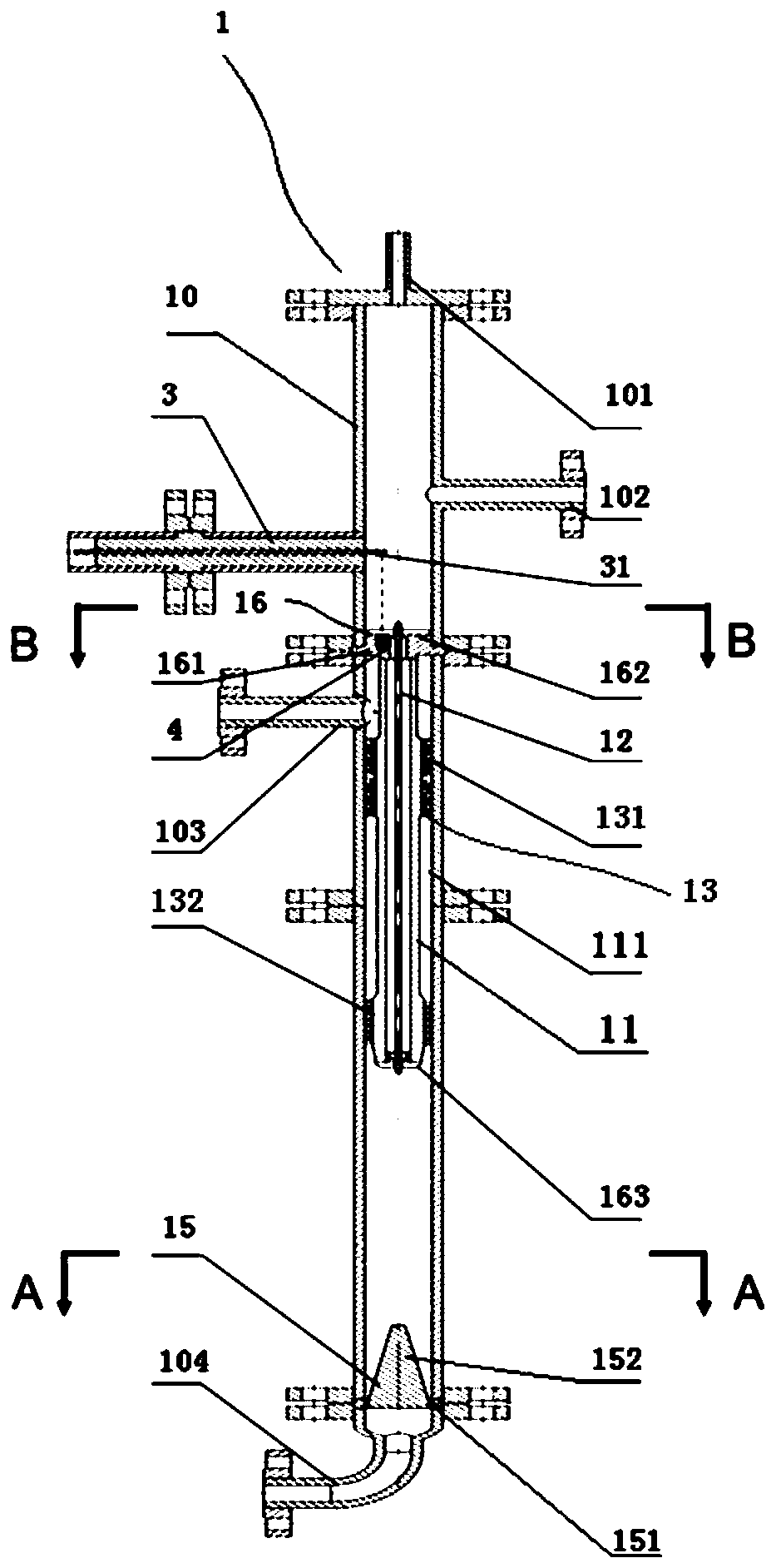
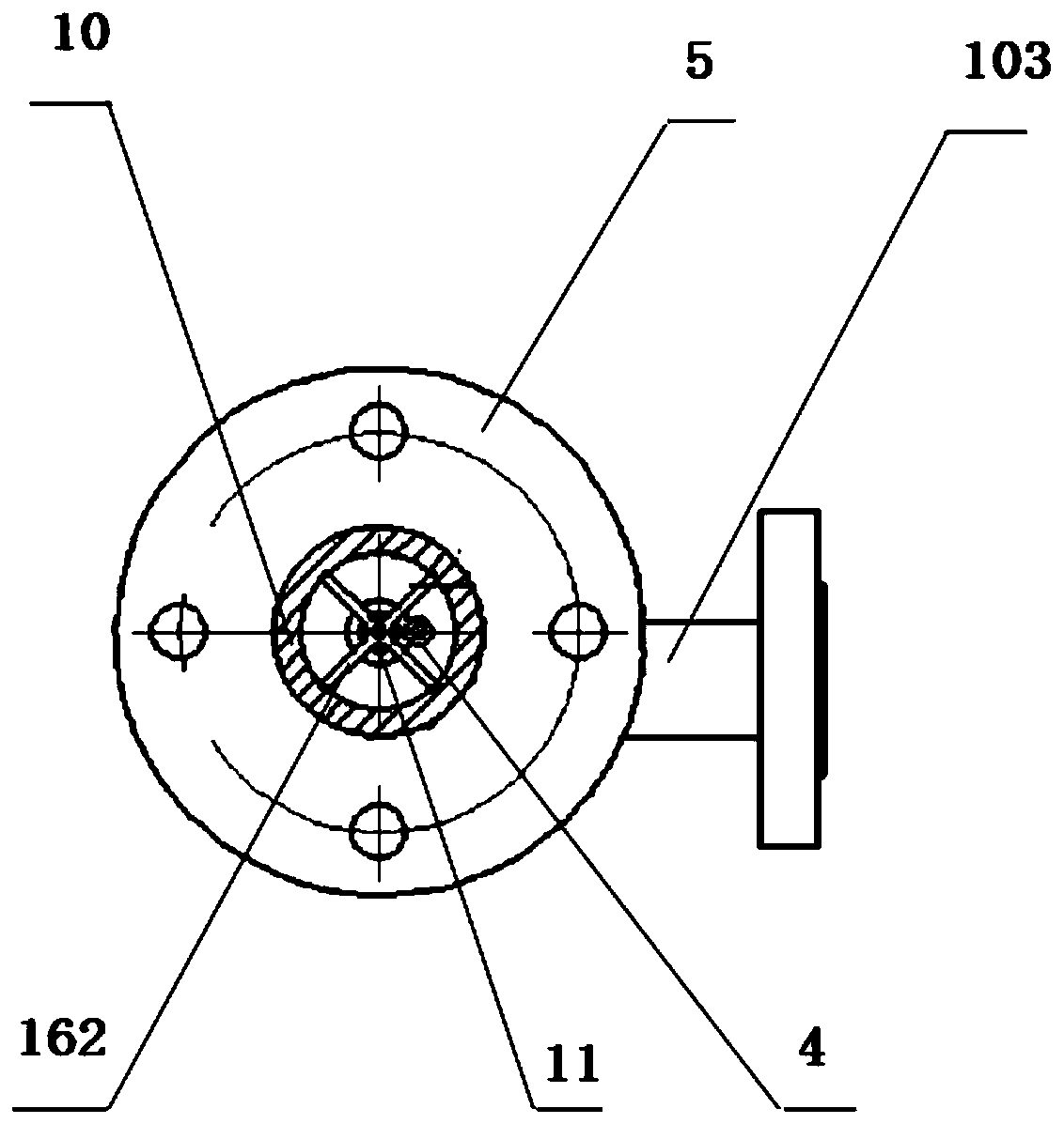
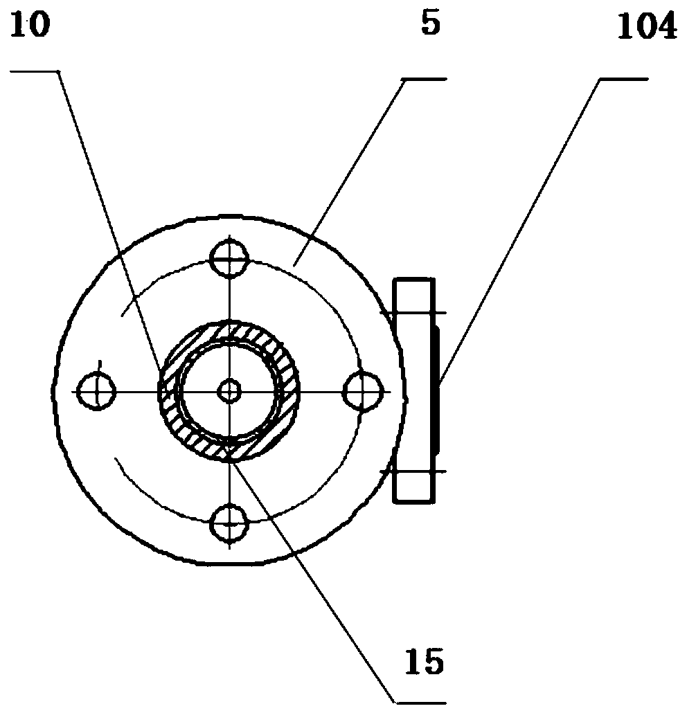
[0035] Such as figure 1 As shown, the embodiment of the present invention provides a tubular electric field demulsification cyclone separator for oil-water separation, including at least one separation unit 1; An air port 101 and an oil outlet 102; an oil-water mixture inlet 103 is arranged in the middle of the outer pipe 10; a water outlet 104 is arranged at the bottom of the outer pipe 10; An annular space 111 is formed between them, and the oil-water mixture inlet 103 communicates with the annular space 111; the central rod 12 is coaxially...


PUM


Abstract

The invention discloses a tubular electric field demulsification cyclone separator for oil-water separation. The cyclone separator comprises at least one separation unit. Each separation unit comprises an outer tube, an inner cylinder, a center rod, an intensified cyclone zone and a flow baffle cone, wherein the upper portion of the outer tube is provided with an exhaust port and an oil outlet, the middle of the outer tube is provided with an oil-water mixture inlet, the lower portion of the outer tube is provided with a water outlet, the inner cylinder is coaxially arranged in the outer tube,an annular space is formed between the inner cylinder and the outer tube, the oil-water mixture inlet is communicated with the annular space, the center rod is coaxially arranged in the inner cylinder, the intensified cyclone zone is formed in the annular space, the flow baffle cone is arranged at the position, at the front end of the water outlet, in the outer tube, the flow baffle cone is provided with flow guide holes communicated with the water outlet, the inner cylinder is connected with an external power source through an oil-resistant and explosion-proof wire, and both the outer tube and the center rod are grounded.

Description

technical field [0001] The invention relates to oil-water separation equipment for oil well production fluid, in particular to a tubular electric field demulsification cyclone separator for oil-water separation. Background technique [0002] The oil well output is mostly a multiphase complex mixture of oil, gas and water, which needs to be treated with a series of treatments such as gas-liquid separation, crude oil dehydration, and sewage deoiling. As far as the dehydration of crude oil is concerned, the process flow of "high-pressure three-phase separator + low-pressure three-phase separator + electric dehydration (salt) device" is often used at present, and the demulsifier (chemical) demulsification is assisted to demulsify. The water content of the exported crude oil is controlled below 0.5%. With the increasing water content of oil well output and the popularization and application of enhanced oil recovery technology in recent years, the quality of crude oil has gradual...

Claims


Application Information

Patent Timeline
IPC IPC(8): C10G33/00C10G33/06C10G33/02
CPCC10G33/00C10G33/02C10G33/06
Inventor 王春升陈家庆姬宜朋尚超张明郑晓鹏王海燕平朝春王艳红
Owner CHINA NAT OFFSHORE OIL CORP
Learn More