Moxibustion device for simulating multiple techniques
A technique of moxibustion and manipulation, applied in heating/cooling reflex point instruments, physical therapy, etc., can solve problems such as inability to function, easy low-temperature burns, etc., and achieve the effect of preserving cultural heritage and good health care effects.
- Summary
- Abstract
- Description
- Claims
- Application Information
AI Technical Summary
Problems solved by technology
Method used
Image
Examples
Embodiment 1
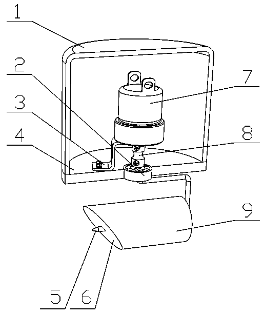
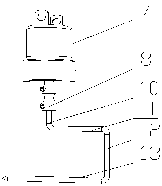
[0030] refer to figure 1 and figure 2 , the rotating mechanism includes a deceleration motor 7 and a moxa needle 5, the deceleration motor 7 is connected to the mounting plate 4 through the motor bracket 3 and bolts, the moxa needle 5 includes a first vertical part 10, a first horizontal part 11, a second vertical part 12 and the second horizontal part 13, the output end of the reduction motor 7 is connected to the upper end of the first vertical part 10 through the connecting sleeve 8 and the connecting screw, and the other end of the lower end of the first vertical part 10 passes through the bearing 2 installed on the mounting plate 4 and One end of the first horizontal portion 11 is connected, the other end of the first horizontal portion 11 is connected to one end of the second vertical portion 12 , and the other end of the second vertical portion 12 is connected to one end of the second horizontal portion 13 .
Embodiment 2
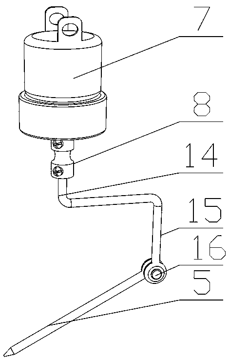
[0032] The difference with embodiment 1 is: refer to image 3 , the rotating mechanism includes a deceleration motor 7, and the moxa stick fixing mechanism also includes a connecting piece, the connecting piece includes a connecting part 14 and an L-shaped part 15, the output end of the decelerating motor is sleeved on one end of the connecting part 14 and fixed by a set bolt, and the other end of the connecting part is connected The horizontal part of the L-shaped part 15, the vertical part of the L-shaped part 15 and one end of the moxa stick 5 are rotatably connected by a rotating shaft 16, and the moxa stick 5 is a columnar structure and is cone-shaped near the burning end of the moxa stick 9.
Embodiment 3
[0034] The difference from Embodiment 1 and Embodiment 2 is that the rotating mechanism includes a deceleration motor 7, a special-shaped connector and a moxa needle 22, and the special-shaped connector includes a connecting sleeve part 18 and an L-shaped bending part 19, and the deceleration motor 7 passes through the motor. The bracket and the bolt are connected to the mounting plate, and the output end of the reduction motor 7 is socketed with the special-shaped connector connecting sleeve portion 18 and fixed by the positioning bolts, and the connecting sleeve portion 18 is connected with the bearing installed on the mounting plate, and the L-shaped bending portion 19 and A One end of bar needle 5 is connected through magnet, and magnet comprises magnet one 20 that is arranged on the vertical part of L-shaped bending part and magnet two 17 that is arranged on one end of moxa needle; magnet one 20 and the opposite surface with magnet two 17 are opposite magnetic poles , the ...
PUM
 Abstract
Description
Claims
Application Information
 - R&D
- Intellectual Property
- Life Sciences
- Materials
- Tech Scout
- Unparalleled Data Quality
- Higher Quality Content
- 60% Fewer Hallucinations
Browse by: Latest US Patents, China's latest patents, Technical Efficacy Thesaurus, Application Domain, Technology Topic, Popular Technical Reports.
© 2025 PatSnap. All rights reserved.Legal|Privacy policy|Modern Slavery Act Transparency Statement|Sitemap|About US| Contact US: help@patsnap.com


