Wind turbine blade deicing method, deicing system and terminal equipment

A technology for wind turbines and blades, which is applied to wind turbines, wind turbine control, mechanical equipment, etc., can solve problems such as jeopardizing the safe operation of wind turbines, overloading 380V power cables, and increasing costs, so as to improve production efficiency and effectively remove ice. , the effect of reducing labor intensity

Active Publication Date: 2020-08-18
湖南风创能源科技有限公司
View PDF6 Cites 0 Cited by
  • Summary
  • Abstract
  • Description
  • Claims
  • Application Information

AI Technical Summary

Problems solved by technology

Due to the importance of the pitch drive device, wind turbine OEMs generally do not allow other high-power equipment to share power cables with the pitch drive device, because when other high-power equipment is running, if the pitch drive device needs high power output to adjust the pitch The distance angle will cause the original 380V power cable to be overloaded, thus endangering the safe operation of the entire fan
If a 380V power cable with a larger capacity is used to meet the power requirements of the pitch drive device and other high-power equipment, the slip ring and cable need to be replaced, and the cost will increase greatly

Method used

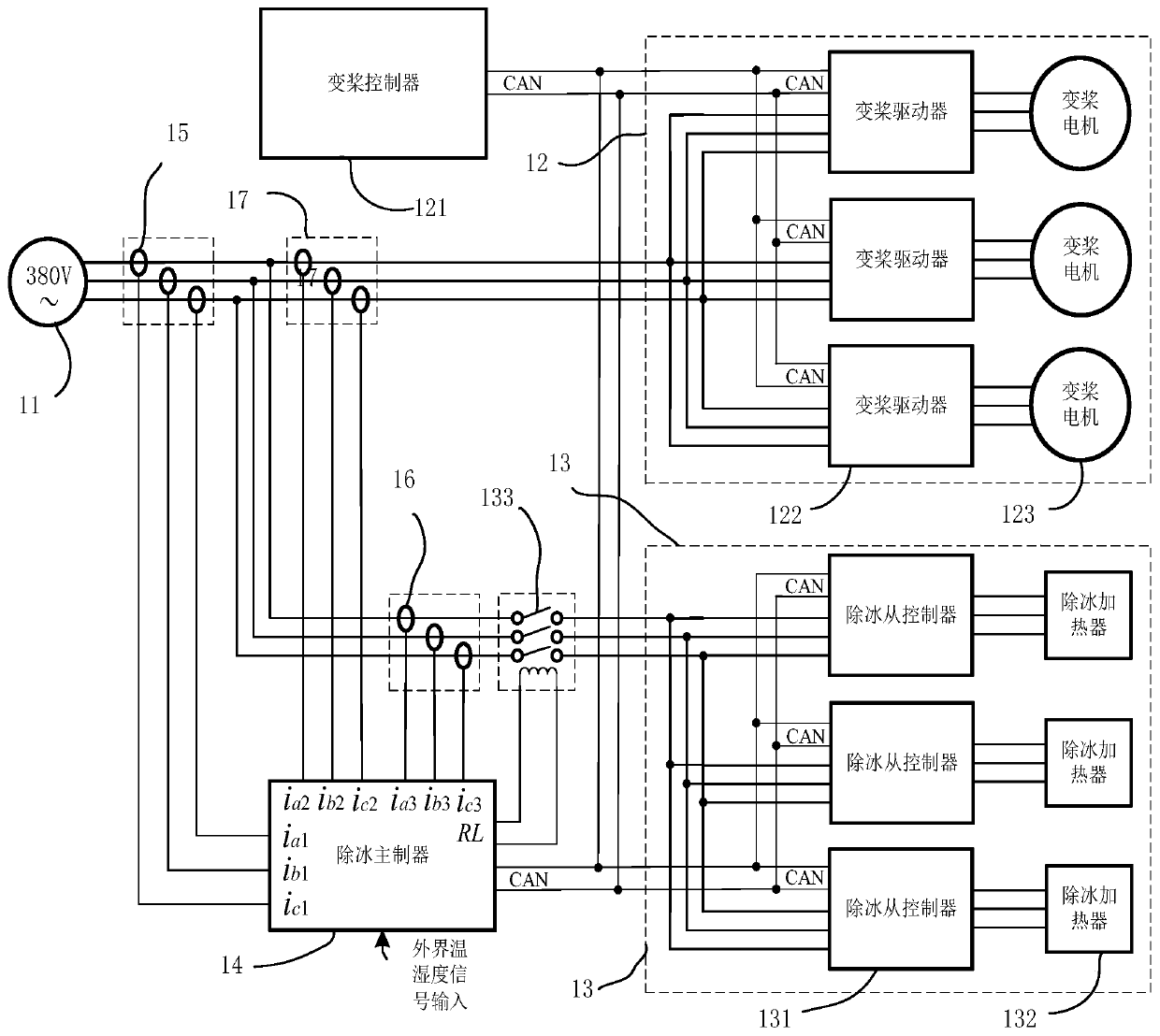
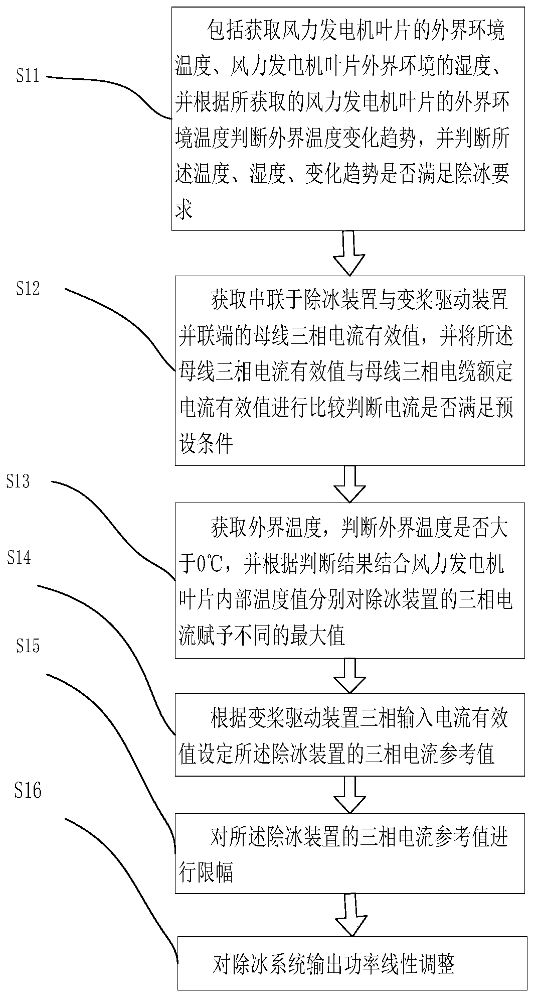
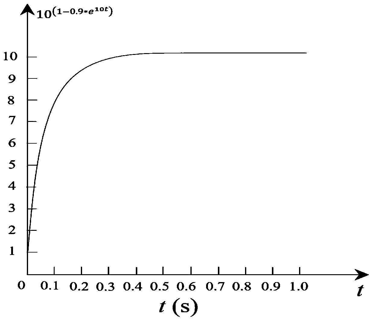

Image

  • Wind turbine blade deicing method, deicing system and terminal equipment
  • Wind turbine blade deicing method, deicing system and terminal equipment
  • Wind turbine blade deicing method, deicing system and terminal equipment

Examples


Embodiment Construction

[0051] In order to make the technical problems, technical solutions and beneficial effects to be solved by the present invention clearer, the present invention will be further described in detail below in conjunction with the accompanying drawings and embodiments. It should be understood that the specific embodiments described here are only used to explain the present invention, not to limit the present invention.

[0052] It should be noted that when an element is referred to as being “fixed” or “disposed on” another element, it may be directly on the other element or be indirectly on the other element. When an element is referred to as being "connected to" another element, it can be directly connected to the other element or indirectly connected to the other element.

[0053] It is to be understood that the terms "length", "width", "top", "bottom", "front", "rear", "left", "right", "vertical", "horizontal", "top" , "bottom", "inner", "outer" and other indicated orientations...


PUM


Abstract

The invention provides a wind driven generator blade ice removing method, an ice removing system and terminal equipment. The ice removing method comprises the steps of obtaining the temperature and the humidity of the external environment of a wind driven generator and a 380V bus three-phase current effective value in a hub; and judging whether to start ice removing or not according to the temperature and humidity values of the external environment, the change tendency of the temperature and the condition if the 380V bus three-phase current effective value exceeds 80% of a bus cable rated current effective value. According to the temperature values of the external environment and in blades, the three-phase current effective value of the ice removing system is set, and the ice removing system is controlled to work in different power states to achieve the best ice preventing and removing effect with the lowest power consumption. The ice removing system comprises an ice removing main controller, an ice removing slave controller, an ice removing heater and other components. The labor amount of cable arrangement and slide ring replacement and the use cost are effectively reduced; and when the reliable operation of a wind turbine generator system is guaranteed, the power generation loss caused by blade icing is reduced, and the enterprise production and management efficiency is improved.

Description

technical field [0001] The invention belongs to the technical field of wind power, and more specifically relates to a method for deicing blades of a wind power generator, a deicing system and terminal equipment. Background technique [0002] In places with low temperature, high humidity and high altitude, wind turbine blades are more likely to freeze. Frozen blades will lead to blade overload and unbalanced load, resulting in a decrease in fan efficiency. Continuing to operate the blades under icing conditions will change the original airfoil of the blades, leading to deterioration of the aerodynamic performance of the blades, resulting in a sharp drop in wind energy capture capacity; when the ice accumulation is severe, the load increases, the vibration intensifies, and even the blades will break, which is harmful to the generator set. cause great harm. Therefore, when the icing is severe, the unit must be disconnected from the grid, and the utilization rate of the unit w...

Claims


Application Information

Patent Timeline
Patent Type & Authority Patents(China)
IPC IPC(8): F03D80/40F03D80/60F03D7/00
CPCF03D7/00F03D80/40F03D80/60F05B2270/328Y02E10/72Y02P70/50
Inventor 范必双王玉凤蒋加伏李泽扬魏国强姚淦洲
Owner 湖南风创能源科技有限公司
Why Eureka
Try Eureka