
Parallel thrust vector exhaust system based on throat offset type pneumatic vector spray pipe

A technology of vectoring nozzle and thrust vectoring, which is applied in the directions of jet propulsion, machine/engine, etc., can solve the problems of unfavorable high-speed flight of aircraft, normal engine, high-efficiency work, and large convergence angle of the outer surface of the nozzle. Improve infrared stealth performance, have universality, and improve the effect of rear body flow field

Active Publication Date: 2019-09-27
NANJING UNIV OF AERONAUTICS & ASTRONAUTICS
View PDF7 Cites 12 Cited by
  • Summary
  • Abstract
  • Description
  • Claims
  • Application Information

AI Technical Summary

Problems solved by technology

This means that as the flight envelope of the aircraft becomes larger and larger, the requirements for the adjustable flow of the nozzle are getting higher and higher, and the inability to adjust the flow of the nozzle with a fixed-geometry nozzle will have more and more adverse effects on the normal and efficient operation of the engine. big impact
At the same time, the convergence angle of the converging section of the front part of the second throat inherent in the throat offset aerodynamic vectoring nozzle is too obvious, resulting in a very large convergence angle of the rear body surface of the nozzle, which will produce an obvious rear body in flight conditions. Resistance, which is extremely unfavorable to the high-speed flight of the aircraft

Method used


Image

  • Parallel thrust vector exhaust system based on throat offset type pneumatic vector spray pipe
  • Parallel thrust vector exhaust system based on throat offset type pneumatic vector spray pipe
  • Parallel thrust vector exhaust system based on throat offset type pneumatic vector spray pipe

Examples


Embodiment

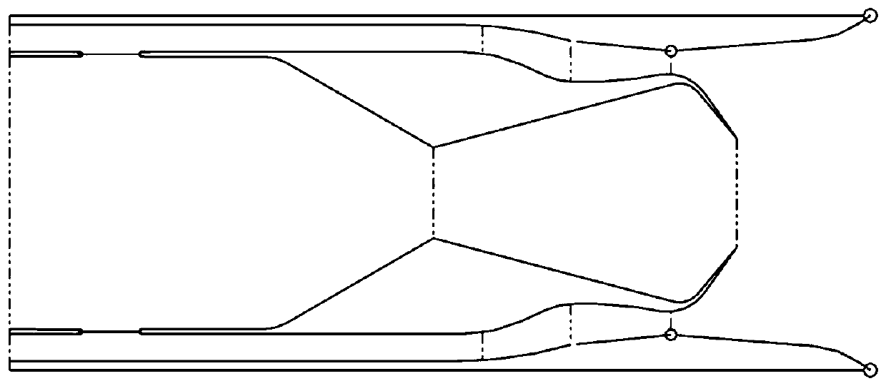
[0056] A typical configuration of a parallel thrust vectoring exhaust system based on throat offset aerodynamic vectoring nozzles is calculated.

[0057] Figure 6 Shown is the numerically calculated Mach number cloud diagram when NPR=4. It can be seen that through the preliminary profile optimization design, when the vector is deflected downward, the airflow of the Laval channel on the upper side channel is not ejected backwards, but is disturbed by the center throat offset aerodynamic vector nozzle Next, flow along the outer wall of the throat offset aerodynamic vector nozzle to achieve deflection. At the same time, the airflow of the lower side channel flows along the tail surface of the nozzle Laval channel and is deflected downward together, thus achieving better vector performance.

[0058] Figure 7 Shown is its data calculation curve. Among them, BDTN basic is the curve of the vector angle of the throat offset aerodynamic vector nozzle with the same profile as the ...


PUM


Abstract

The invention discloses a parallel thrust vector exhaust system based on a throat offset type pneumatic vector spray pipe. The system comprises the throat offset type pneumatic vector spray pipe and an adjustable Laval spray pipe arranged on the outer side of the throat offset type pneumatic vector spray pipe, through an inner and outer nested parallel structure, the thrust vector is generated by the throat offset type pneumatic vector spray pipe, and the flow regulation function is realized by the Laval spray pipe connected in parallel on the outer side. According to the parallel thrust vector exhaust system based on the throat offset type pneumatic vector spray pipe, different functions of the spray pipes are realized by utilizing different parts, so that the spray pipes have the characteristics that the thrust vector is efficient, the wide-range flow is adjustable, and infrared signals are reduced; and the smooth transition molded surface is designed, so that the exhaust system has relatively good thrust performance and vector performance at the same time in a wide working range, then the evolution of a fixed geometric thrust vector spray pipe is realized, the flight envelope of an aircraft is expanded, and the use requirements of the aircraft are better met.

Description

technical field [0001] The invention relates to a parallel thrust vectoring exhaust system based on a throat offset aerodynamic vectoring nozzle, belonging to the technical field of advanced thrust vectoring nozzles of aero-engines. Background technique [0002] With the development of science and technology and the improvement of actual demand, more and more thrust vectoring aeroengines will be used in future aircraft. The core of the thrust vectoring aeroengine to realize the thrust vectoring function is the thrust vectoring nozzle. The traditional mechanical thrust vectoring nozzle has complex structure, poor reliability and troublesome maintenance. Therefore, it is imminent to develop a thrust vectoring nozzle with simple structure, light weight and good maintainability. [0003] At present, the fluid thrust vectoring nozzle has gradually become the research focus and research focus of various countries due to its simple structure and light weight, and will enter engin...

Claims


Application Information

Patent Timeline
IPC IPC(8): F02K1/15F02K1/00F02K1/09F02K1/12
CPCF02K1/006F02K1/008F02K1/09F02K1/12F02K1/1207F02K1/1223F02K1/15
Inventor 黄帅徐惊雷汪阳生蒋晶晶潘睿丰陈匡世
Owner NANJING UNIV OF AERONAUTICS & ASTRONAUTICS
Learn More