A Bidirectional Collection System for Centrifugal Spinning
A technology of centrifugal spinning and collection system, which is applied in the field of two-way collection system of centrifugal spinning, which can solve the problems of unfavorable follow-up processing and poor collection effect, and achieve the effect of convenient follow-up processing, strong guiding, and favorable removal of spinning
- Summary
- Abstract
- Description
- Claims
- Application Information
AI Technical Summary
Problems solved by technology
Method used
Image
Examples
Embodiment 1
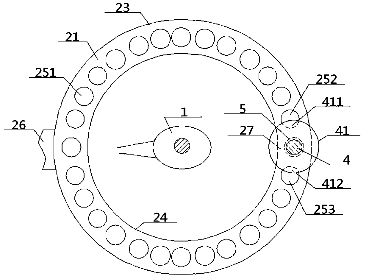
[0049] see Figure 1 to Figure 4 , a two-way collection system for centrifugal spinning, comprising an air jet ring plate 2, a bottom collecting portion 3 and a longitudinal collection rod 4; the air jet ring plate 2 is a hollow structure, including a top ring plate 21, a bottom ring plate 22 and a The outer ring wall 23, the inner ring wall 24 between the two, the top ring plate 21, the outer ring wall 23, the bottom ring plate 22, and the inner ring wall 24 together form the same ring disc cavity 25, and the inner ring wall 24 encloses An inner ring cavity 241 with upper and lower openings, the top ring plate 21 is provided with a plurality of ejection air holes 251 communicating with the inner cavity 25 of the ring disc, and an inserting rod barrel 5 is arranged inside the inner cavity 25 of the ring disc. The top of the rod barrel 5 is connected with the upper rod opening 211 provided on the top ring plate 21, and the bottom end of the inserting rod barrel 5 is connected w...
Embodiment 2
[0051] Basic content is the same as embodiment 1, the difference is:
[0052] The top and the bottom of the vertical collecting rod 4 are vertically connected with the upper limit plate 41 and the lower limit plate 42 respectively, the width of the upper limit plate 41 is greater than the width of the top ring plate 21, and the width of the lower limit plate 42 is greater than The diameter of the lower rod port 221. The upper limit plate 41 is circular, and the ejection air holes 251 on both sides of the upper rod opening 211 are respectively the No. 1 air hole 252 and the No. 2 air hole 253. The No. 1 air hole 252, the No. 2 air hole 253 and the upper limit plate 41 are on the top The projections on the ring plate 21 contact each other to form a first contact area 411 and a second contact area 412; the connection between the lower limit plate 42 and the bottom end of the longitudinal collecting rod 4 is a flexible connection. Preferably, the area of the first contact area ...
Embodiment 3
[0054] Basic content is the same as embodiment 1, the difference is:
[0055] The longitudinal collecting rod 4 is a hollow structure, the inside of the longitudinal collecting rod 4 is provided with a coaxial longitudinal rod inner chamber 43, and the rod wall of the longitudinal collecting rod 4 is provided with a longitudinal rod air hole 44 communicating with the longitudinal rod inner chamber 43, A lower plate hole 421 communicating with the inner cavity 43 of the longitudinal rod is defined in the middle of the lower limiting plate 42 .
PUM
 Abstract
Description
Claims
Application Information
 - R&D
- Intellectual Property
- Life Sciences
- Materials
- Tech Scout
- Unparalleled Data Quality
- Higher Quality Content
- 60% Fewer Hallucinations
Browse by: Latest US Patents, China's latest patents, Technical Efficacy Thesaurus, Application Domain, Technology Topic, Popular Technical Reports.
© 2025 PatSnap. All rights reserved.Legal|Privacy policy|Modern Slavery Act Transparency Statement|Sitemap|About US| Contact US: help@patsnap.com


