
Electric stewing pot

An electric stewing and outer pot technology, which is applied to cooking utensils, household appliances, applications, etc., can solve the problems of poor sealing performance of the pot cover to the cooking cavity, reducing the heating efficiency of the electric stew pot, and poor sound insulation performance of the pot cover. The effect of massive loss of steam, ease of appearance proportions, reduced design and adjustment difficulty

Pending Publication Date: 2019-09-27
BEAR ELECTRICAL APPLIANCE CO LTD +1
View PDF0 Cites 9 Cited by
  • Summary
  • Abstract
  • Description
  • Claims
  • Application Information

AI Technical Summary

Problems solved by technology

But this kind of electric stew pot has the following problems: (1) because the pot cover is a single-layer structure, its heat insulation performance is relatively poor, and it is easy to cause the heat in the cooking cavity to be lost to the outside, reducing the heating efficiency of the electric stew pot; (2) The sealing performance of the pot cover to the cooking cavity is poor. During the cooking process of the electric stew pot, a large amount of steam in the cooking cavity will be lost. In order to ensure the cooking effect, the volume of the cooking cavity needs to be increased to store water, resulting in a larger volume of the outer pot. The overall appearance of the product is uncoordinated, and the aesthetics are poor; (3) When the water boils to generate air bubbles and impact the inner tank, it will generate noise due to the formation of resonance, and the sound insulation performance of the single-layer structure of the pot lid is poor, causing the noise to spread to the electric stew Out of the pot, reduce the user experience of using the electric stew pot

Method used


Image

  • Electric stewing pot
  • Electric stewing pot
  • Electric stewing pot

Examples


Embodiment approach

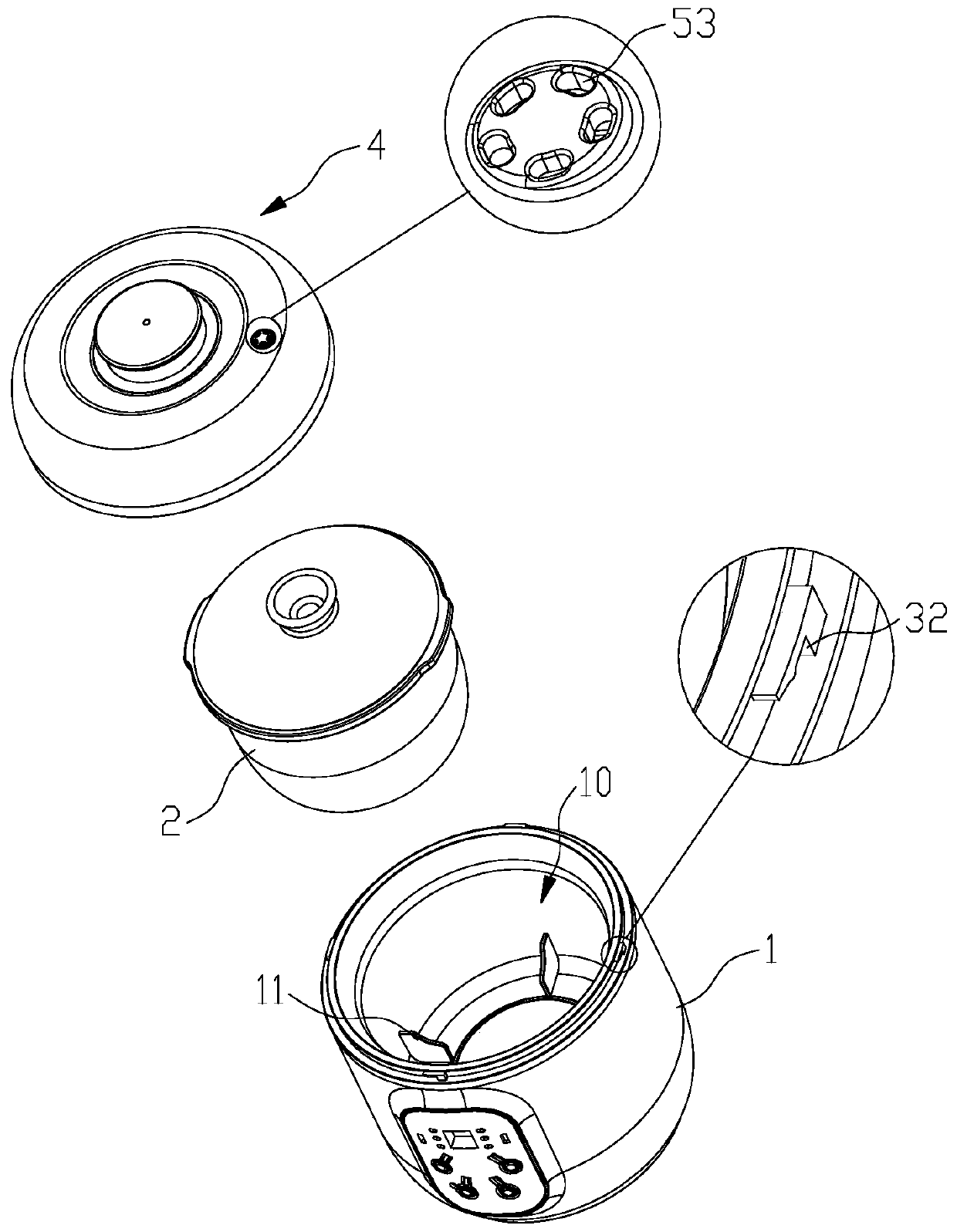
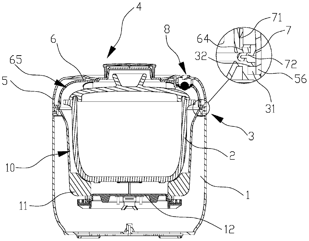
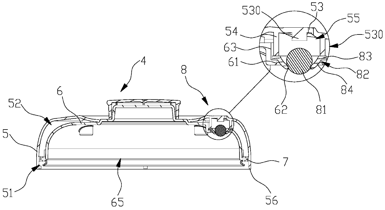
[0030] see Figure 1 to Figure 5, an electric stew pot according to this embodiment, comprising a pot cover 4, an outer pot 1 and an inner pot 2; Component 12; the inner tank 2 is set in the heating inner cavity 10; the pot cover 4 is sealed on the upper opening of the outer pot 1, and the pot cover 4 is provided with an inward valve structure 8, so The inward valve structure 8 includes an exhaust hole 53, a gas exchange channel 55, an air inlet 62 and a pressurized ball 81; the exhaust hole 53 is arranged on the pot cover 4 for communicating with the outside world, and the gas exchange The channel 55 is arranged on the pot cover 4 and extends along the lower side of the pot cover 4 , the gas exchange channel 55 communicates with the exhaust hole 53 , and the air inlet 62 is arranged at the lower end of the gas exchange channel 55 And communicated with the heating inner cavity 10 , the pressurized ball 81 is movably arranged in the gas exchange channel 55 for sealing or openi...


PUM


Abstract

The invention provides an electric stewing pot. The electric stewing pot comprises a pot cover, an outer pot body and an inner container; the outer pot body is provided with a heating inner cavity with an opening in the upper side, and a heating assembly is arranged at the bottom of the heating inner cavity; the inner container is arrange in the heating inner cavity; the upper side opening of the outer pot body is covered with the pot cover, an inward valve structure is arranged on the pot cover, and the inward valve structure comprises an exhaust hole, a gas exchange channel, an air inlet and a pressurizing ball; and the exhaust hole is formed in the pot cover and is used for communicating with the outside, the gas exchange channel is formed in the pot cover and extends along the lower side of the pot cover, the gas exchange channel communicates with the exhaust hole, the air inlet is formed in the lower end of the gas exchange channel and communicates with the heating inner cavity, and the pressurizing ball is movably arranged in the gas exchange channel and is used for sealing or opening the air inlet according to the pressure in the heating inner cavity. According to the electric stewing pot, the heat insulation performance and the sealing performance of the pot cover are good, so that food materials in the inner container are heated evenly, and the original taste and flavor can be maintained.

Description

technical field [0001] The invention relates to the field of electric stew pot devices, in particular to an electric stew pot. Background technique [0002] With the continuous development of society, people are more and more fond of taking time out of daily life to carefully cook food. Electric cooking equipment is often used in the process of cooking food. Common electric cooking equipment includes electric rice cookers, pressure cookers and electric cookers. Stewing pot, the working principle of the electric rice cooker is to use the heating components on the outer pot to heat the inner pot, so that the inner pot is heated to cook the ingredients in the inner pot; and the pressure cooker and the electric rice cooker with a pressure valve The working principle is to use the heating element on the outer pot to heat the inner pot, and at the same time use the upper cover to seal the upper opening of the inner pot, so that the internal pressure of the inner pot is increased a...

Claims


Application Information

Patent Timeline
Patent Type & Authority Applications(China)
IPC IPC(8): A47J27/08A47J27/086
CPCA47J27/08A47J27/0802A47J27/086
Inventor 李一峰何致勇
Owner BEAR ELECTRICAL APPLIANCE CO LTD
Learn More