Square dual-frequency microstrip patch antenna

A microstrip patch antenna, square technology, applied in the direction of antenna grounding switch structure connection, radiation element structure, etc., can solve the problems of not improving the axial ratio performance, affecting the circular polarization of the antenna, and poor antenna axial ratio performance, etc., to achieve Ease of processing, design and assembly, improved circular polarization performance, and stable phase center

Inactive Publication Date: 2019-09-24
江苏三和欣创通信科技有限公司
View PDF8 Cites 1 Cited by
  • Summary
  • Abstract
  • Description
  • Claims
  • Application Information

AI Technical Summary

Problems solved by technology

[0006] The invention patent with the patent number US7385555 also uses a single-layer or double-layer microstrip patch antenna design, but the probe directly contacts the feeding method, and in the literature, the axial ratio performance is not improved, which affects the circular polarization of the antenna
After actual simulation and calculation, it is found that the axial ratio performance of the antenna in this paper is relatively poor. In addition, the invention has a narrow working bandwidth and low gain.

Method used


Image

  • Square dual-frequency microstrip patch antenna
  • Square dual-frequency microstrip patch antenna
  • Square dual-frequency microstrip patch antenna

Examples


Embodiment 1

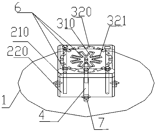
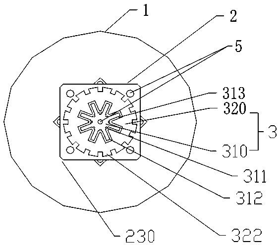
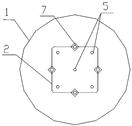
[0038] Such as Figure 1-3 As shown, a square dual-frequency microstrip patch antenna includes: a conductive ground plane 1, a dielectric substrate 2 disposed on the conductive ground plane, a radiation sheet 3 disposed on the top of the dielectric substrate, and a dielectric substrate surrounded by Several feeding probes 4 on the side wall;

[0039] The radiating sheet 3 includes a concentric first radiating sheet 310 and a second radiating sheet 320, the first radiating sheet resonates to generate a high frequency, and the second radiating sheet resonates to generate a low frequency, forming a high and low frequency band;

[0040] The first radiating sheet 310 is a gear-shaped thin sheet, and a groove 311 is processed at the center of each alveolar bottom of the gear-shaped first radiating sheet;

[0041] The second radiating sheet 320 is a circular thin sheet with jagged outer edges, the second radiating sheet is larger than the first radiating sheet, and the middle part o...

Embodiment 2

[0055] The feeding probe feeds the first radiating sheet and the second radiating sheet in a coupled feeding manner.

[0056] Such as Figure 4 , using 4 orthogonal feeding probes, every two adjacent ones undergo signal phase shifting, and a good circularly polarized signal output is obtained after combining, where Hybrid is a coupler with a phase shift of 90 degrees.

[0057] Four feeding probes have good circular polarization performance, and the phase center is stable due to the symmetry of the antenna.


PUM

PropertyMeasurementUnit
Thicknessaaaaaaaaaa
Thicknessaaaaaaaaaa
Thicknessaaaaaaaaaa

Abstract

The invention relates to a square dual-frequency microstrip patch antenna. The square dual-frequency microstrip patch antenna comprises a conductive grounding plane, a cube-shaped dielectric substrate, a radiating sheet and a plurality of feed probes which are arranged in turn, wherein the radiating sheet includes a first radiating sheet and a second radiating sheet, the first radiating sheet is a gear-shaped sheet, and the bottom of each tooth slot of the gear-shaped first radiating sheet is processed with a groove at the center; the second radiating sheet is a circular sheet with the outer edge being serrated, the second radiating sheet is greater than the first radiating sheet, the middle part of the second radiating sheet is processed with an opening matched with the first radiating sheet in shape, and the first radiating sheet is arranged in the opening. The square dual-frequency microstrip patch antenna can be fixed extremely stably, adopts a single-layer antenna structure, has simple structure and higher reliability, and is more convenient to process, design and assemble. The processing is simple, the polarization performance of the antenna is improved, the phase center is stable, and the antenna is particularly suitable for precise measurement of the GNSS (Global Navigation Satellite System) and terminal equipment of the positioning system.

Description

technical field [0001] The invention belongs to the technical field of wireless communication, and in particular relates to a square dual-frequency microstrip patch antenna. Background technique [0002] The current satellite navigation and positioning equipment is widely used in fields such as positioning, measurement, timing, high-precision agriculture and intelligent transportation. In order to obtain high-precision positioning requirements above the decimeter level, navigation equipment generally adopts RTK (real-time dynamic differential method) technology. And axle ratio bandwidth), and more compact size, while processing and manufacturing should be simple. Microstrip patch antennas are widely used because of their small shape, low cost, easy conformality, easy processing, and easy realization of circular polarization. [0003] Traditional microstrip antennas generally implement dual-band by stacking, that is, generally one layer implements a working frequency band, ...

Claims


Application Information

Patent Timeline
IPC IPC(8): H01Q1/36H01Q1/38H01Q1/50
CPCH01Q1/36H01Q1/38H01Q1/50
Inventor 施静李庚禄吴艳杰李铎张慧龙刘兆华娟
Owner 江苏三和欣创通信科技有限公司
Why Eureka
Try Eureka