
Electron beam detecting system

A detection system and electron beam technology, applied in the field of irradiation processing, can solve the problems of different measurement accuracy and low measurement accuracy of high-current electron beam, so as to reduce inaccuracy, improve detection accuracy, and reduce electromagnetic interference. Effect

Inactive Publication Date: 2019-09-24
HUAZHONG UNIV OF SCI & TECH
View PDF8 Cites 2 Cited by
  • Summary
  • Abstract
  • Description
  • Claims
  • Application Information

AI Technical Summary

Problems solved by technology

Therefore, it is necessary to quickly and accurately measure the uniformity index of the irradiation; but the measurement accuracy of the existing measurement schemes is different, especially the measurement accuracy of the high-intensity electron beam is particularly low

Method used


Image

  • Electron beam detecting system
  • Electron beam detecting system
  • Electron beam detecting system

Examples


Embodiment Construction

[0037] The technical solutions of the present invention will be further described in detail below in conjunction with the accompanying drawings and specific embodiments.

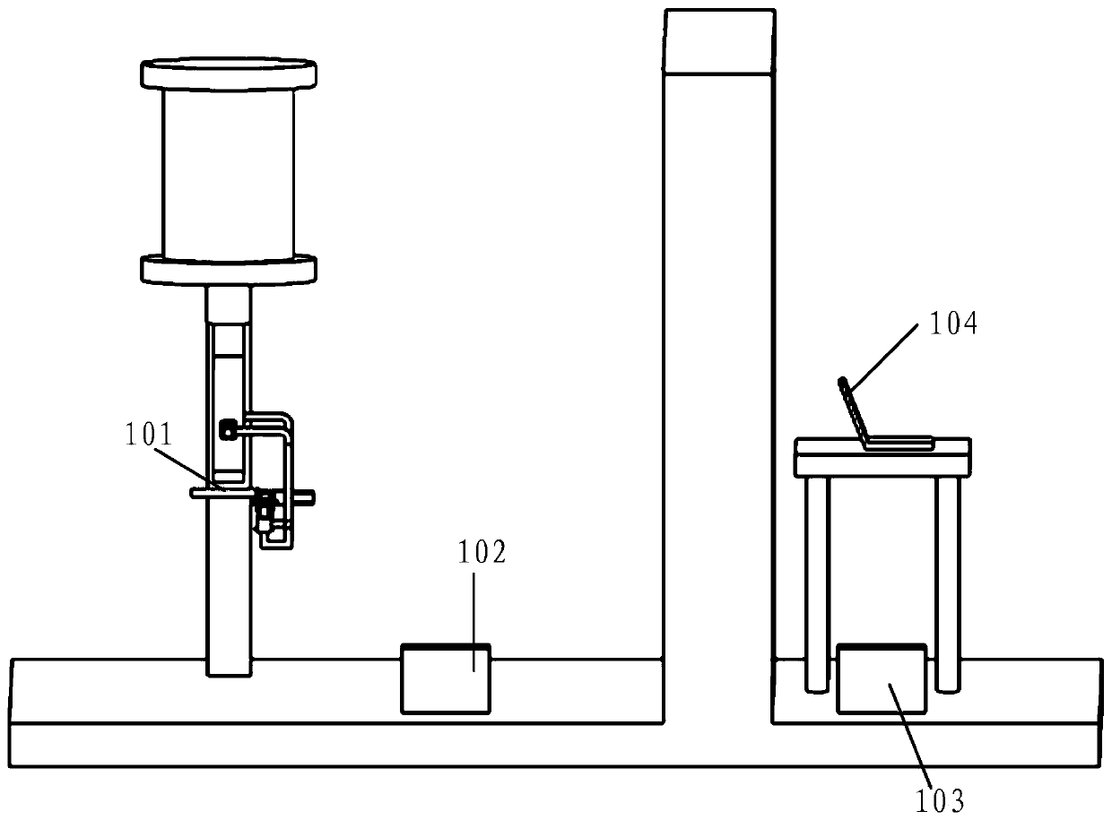
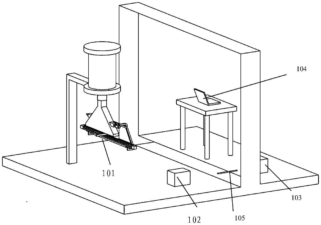
[0038] Such as figure 1 and figure 2 As shown, the present embodiment provides an electron beam detection system, including:

[0039] The electron collection device 101 is located in the shielding room together with the electron beam accelerator, and is used to detect the electron beam intensity radiated by the electron beam accelerator to obtain the first signal;

[0040] The sampling box 102 is located in the shielding room and is connected to the electron collection device 101 for receiving the first signal and converting the first signal into an optical signal that reflects the uniformity of the electron beam irradiation. second signal;

[0041] The communication box 103 is located outside the shielding room and is connected to the sampling box 102 through an optical fiber 105 for receiving the secon...


PUM


Abstract

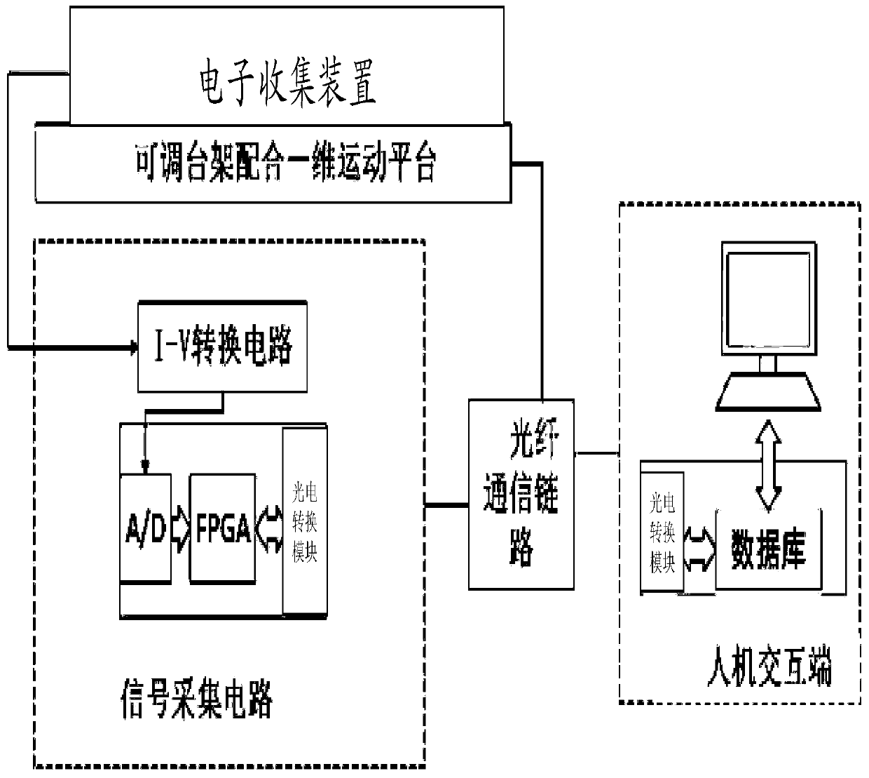
The embodiment of the invention provides an electron beam detecting system comprising an electron collecting device, a sampling box, a communication box, and a controller. The electron collecting device, together with an electron beam accelerator, is arranged in a shielding room and is used for detecting the intensity of an electron beam radiated by the electron beam accelerator to obtain a first signal. The sampling box that is arranged in the shielding room and is connected with the electron collecting device is used for receiving the first signal and converting the first signal into a second signal that is in an optical signal manner and can reflect the irradiation uniformity of the electron beam. The communication box that is arranged outside the shielding room and is connected with the sampling box by a fiber is used for receiving the second signal by the fiber and converting the second signal into a third signal in an electric signal manner. The controller that is arranged outside the shielding room and is connected with the communication box is used for receiving the third signal. Therefore, the detection control of the electron beam is realized.

Description

technical field [0001] The invention relates to the technical field of radiation processing, in particular to an electron beam detection system. Background technique [0002] Irradiation technology is the use of the interaction between rays and substances, ionization and excitation of activated atoms and activated molecules, so that a series of physical, chemical, and biochemical changes occur between them and substances, resulting in the degradation, polymerization, crosslinking, and degradation of substances. and undergo modification. Due to the superiority of its processing, irradiation technology has achieved rapid development, and the processing objects are becoming more and more extensive. The processed product itself has a certain volume, the distance from the source is not equal, and the absorbed dose in the same batch of products is uneven. When the absorbed dose of the product is lower than the effective dose, the required radiation effect cannot be produced, and...

Claims


Application Information

Patent Timeline
Patent Type & Authority Applications(China)
IPC IPC(8): G01T1/29G01T7/00
CPCG01T1/29G01T7/00
Inventor 黄江张力戈樊明武余调琴李海军丁宙左晨杨军熊永前齐伟赵龙曹磊胡桐宁
Owner HUAZHONG UNIV OF SCI & TECH
Learn More