Air source heat pump system

An air source heat pump, heat exchange tube technology, applied in lighting and heating equipment, compressors with reversible cycle, damage protection, etc., can solve the problems of liquid refrigerant backflow, poor suction pressure refrigeration efficiency, etc. , The effect of improving operating efficiency and high reliability

Pending Publication Date: 2019-09-24
SHANGHAI COMER MACHINERY
View PDF0 Cites 0 Cited by
  • Summary
  • Abstract
  • Description
  • Claims
  • Application Information

AI Technical Summary

Problems solved by technology

[0004] The technical problem to be solved by the present invention is to provide an air source heat pump system in order to overcome the defects of the prior art that the liquid refrigerant returns to the compressor after the defrosting mode ends, the suction pressure and the refrigeration efficiency of the system are poor

Method used


Image

  • Air source heat pump system
  • Air source heat pump system
  • Air source heat pump system

Examples


Embodiment Construction

[0024] A preferred embodiment will be given below, and the present invention will be described more clearly and completely in conjunction with the accompanying drawings.

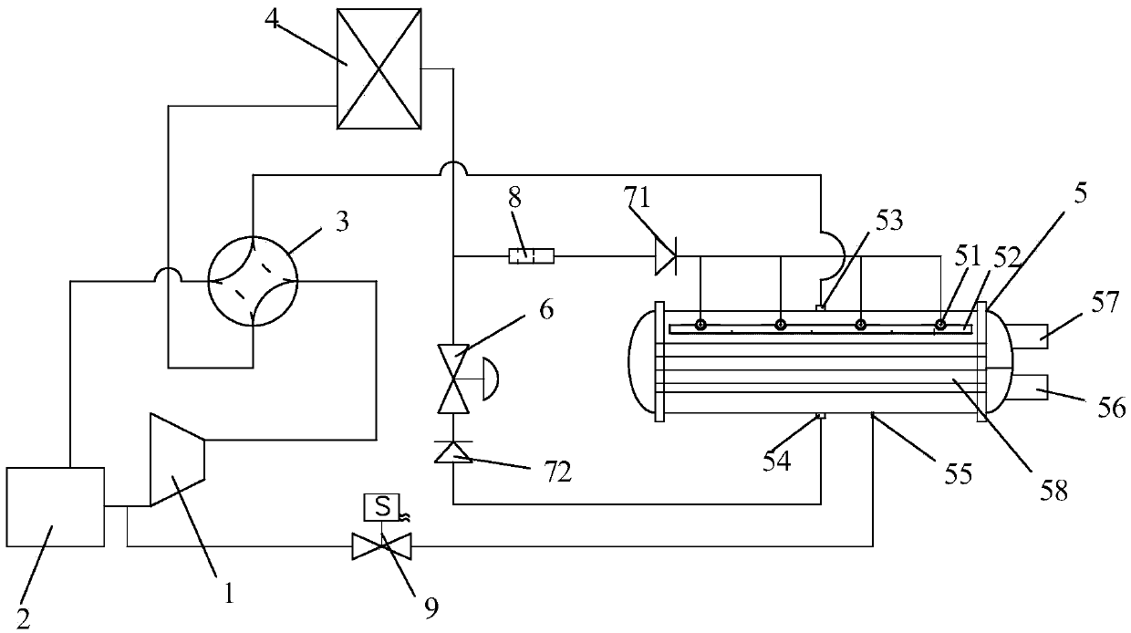
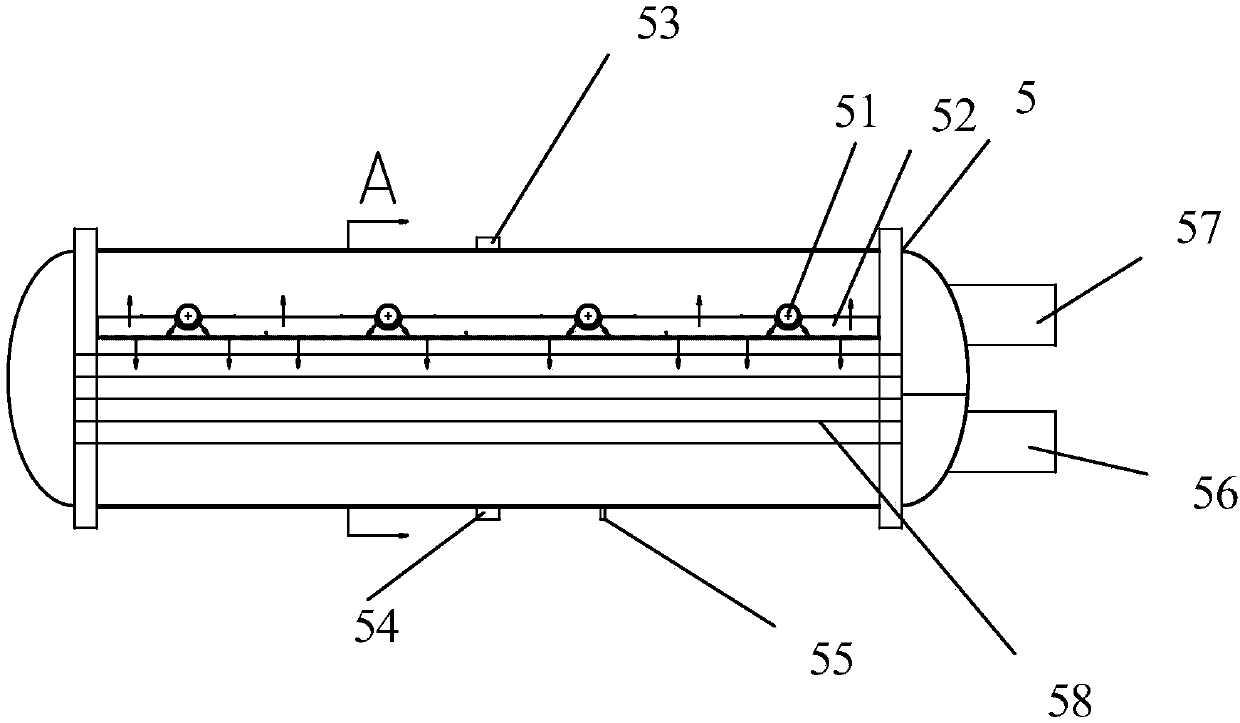
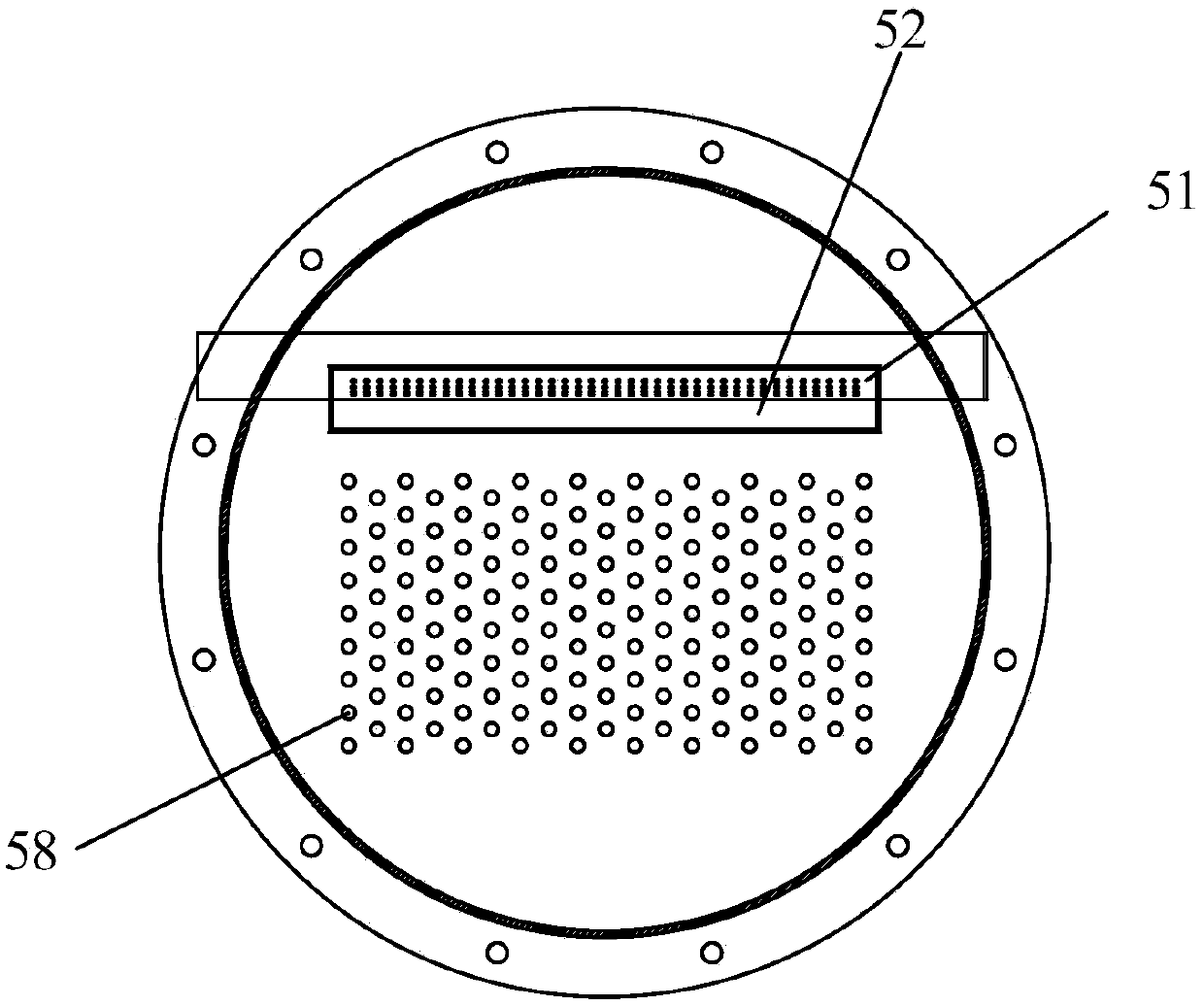
[0025] Such as Figure 1-Figure 3 As shown, the present invention includes an air source heat pump system, including a compressor 1, a finned heat exchanger 4, a shell-and-tube heat exchanger 5, and a gas-liquid separator 2 communicated with the compressor 1. It is characterized in that the shell-and-tube The heat exchanger 5 includes an air pipe 53, a liquid pipe 54, a heat exchange pipe 58, and a liquid separator. The air source heat pump system also includes a four-way valve 3, which is connected to the compressor 1, the gas-liquid separator 2, and the fins respectively. The fin heat exchanger 4 and the gas pipe 53 are connected, wherein,

[0026] Such as figure 1 As shown, the fin heat exchanger 4 communicates with the liquid separator through the orifice plate 8 and the first one-way valve 71; at the ...


PUM


Abstract

The invention provides an air source heat pump system. The air source heat pump system comprises a compressor, a fin heat exchanger, a shell tube heat exchanger and a gas-liquid separator, wherein the shell tube heat exchanger comprises a gas tube, a liquid tube, a heat exchange tube and a liquid separating device, the air source heat pump system further comprises a four-way valve, the four-way valve is correspondingly communication with the compressor, the gas-liquid separator, the fin heat exchanger and the gas pipe, the fin heat exchanger is in communication with the liquid separating device through a orifice plate and a first one-way valve; the fin heat exchanger is in communication with the liquid tube through an expansion valve and a second one-way valve; the first one-way valve is used for the one-way conduction of the fin heat exchanger to the liquid separating device; the second one-way valve is used for the one-way conduction of the liquid pipe to the fin heat exchanger. By the adoption of the system, a liquid storage device of the liquid refrigerant does not need to be added in the system, so that the cost is saved; a large amount of liquid refrigerant cannot flow back to the compressor after defrosting is finished; during the refrigeration mode, the refrigerant running shell pass does not need to be subjected to suction superheat, so that the air suction pressure and the operation efficiency of the refrigeration mode are improved; and the overall use valve of the system is less, and the reliability is high.

Description

technical field [0001] The invention relates to an air source heat pump system. Background technique [0002] When the air source heat pump system runs in the heating mode for a long time, the surface of the fins will frost. The fin frosting is detected through the system parameters (temperature, pressure, etc.), and the system enters the defrosting mode when the defrosting conditions are met. When the existing system exits defrosting, a large amount of liquid refrigerant is likely to return to the compressor or temporarily store in the gas-liquid separator, which increases costs and is not conducive to system reliability. [0003] When the air source heat pump system operates in cooling mode, a dry shell-and-tube heat exchanger is generally used as the evaporator. At this time, the refrigerant flows through the tube side of the shell-and-tube heat exchanger (inside the heat exchange tube), and the shell side uses water or other refrigerants. . Considering the problem of ...

Claims


Application Information

Patent Timeline
IPC IPC(8): F25B13/00F25B47/02
CPCF25B13/00F25B47/02F25B2347/02
Inventor 王乐民张恩启杨凯远项嘉杰
Owner SHANGHAI COMER MACHINERY
Why Eureka
Try Eureka