
Systems and methods for real-time imaging

一种计算机系统、图像的技术,应用在用于放射诊断的仪器、2D图像的生成、应用等方向,能够解决计算能力不适用实时应用等问题

Active Publication Date: 2019-09-20
ELEKTA AB
View PDF5 Cites 3 Cited by
  • Summary
  • Abstract
  • Description
  • Claims
  • Application Information

AI Technical Summary

Problems solved by technology

Using a "cine CBCT" rather than a "cine projection" solution, it is possible to detect lower contrast targets where fiducials are usually not required, but again, the computing power required to perform such calculations may not be suitable for real-time applications

Method used


Image

  • Systems and methods for real-time imaging
  • Systems and methods for real-time imaging
  • Systems and methods for real-time imaging

Examples


Embodiment approach

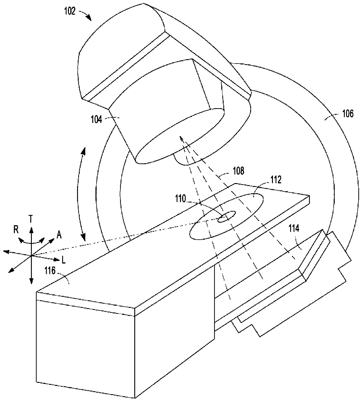
[0116] In some embodiments of the present disclosure, an MRI linac may be used instead of a conventional linac with CBCT imaging. Figure 11 A partial cross-sectional view of a combined radiation therapy system 602 and magnetic resonance (MR) imaging system 630 is depicted. The MR imaging system 630 may define a bore extending along an axis (A), and the radiation therapy system 602 may include a radiation therapy output 604 configured to direct a radiation therapy beam 608 toward an isocenter 610 within the bore. The radiation therapy output 604 may include a collimator 624 that may steer and / or shape the radiation therapy beam 608 to direct the beam 608 to a target region within the patient. The patient may be supported by a surface such as a platform that may be positioned in one or more of an axial direction (A), a lateral direction (L), or a transverse direction (T). One or more portions of radiation therapy system 602 may be mounted on gantry 606 ; for example, radiation...


PUM


Abstract

Embodiments of the present disclosure are directed to a system for generating three-dimensional images of a target region of a patient. The system may include at least one computer system. The computer system may be configured to receive a plurality of non-parallel projection images of the target region of the patient, convert the plurality of non-parallel projection images into a non- spatial domain, reconstruct a three-dimensional image from the plurality of non- parallel projection images in the non-spatial domain, and convert the reconstructed three-dimensional image from the non-spatial domain to the spatial domain.

Description

[0001] related application [0002] This application claims priority to US Application Serial No. 15 / 357,193, filed November 21, 2016, the entire disclosure of which is incorporated herein by reference in its entirety. technical field [0003] Aspects of the present disclosure relate generally to radiation therapy systems, and in particular to methods and systems for real-time imaging and motion management for use with, for example, radiation therapy systems. Background technique [0004] Radiation therapy (also known as radiotherapy) may be used in the treatment of cancer or other conditions. Radiation therapy involves delivering prescribed doses of radiation to a targeted area of ​​a patient, for example, to a tumor or other cancerous tissue. The target area may be imaged prior to delivery of radiation therapy, and a treatment plan may be developed based on, for example, the size, location and / or orientation of the target and surrounding structures. Radiation can then b...

Claims


Application Information

Patent Timeline
Patent Type & Authority Applications(China)
IPC IPC(8): G06T11/00G06T7/00G16H30/40A61B6/00A61B6/03A61B6/04
CPCG06T11/006G06T2211/421G06T2211/428A61B6/5288A61B6/541A61B6/0487A61B6/032A61B6/4085A61B6/5205G06T7/0012G06T11/003G06T2207/10081
Inventor 马丁·埃米尔·拉歇内
Owner ELEKTA AB
Learn More