Test system applied to LED lamp test fixture

A test fixture and test system technology, applied in the use of semiconductor lamps, electrical components, electroluminescence light sources, etc., can solve the problems of low test efficiency and insufficient reliability of LED lamps

Inactive Publication Date: 2019-09-20
广州市微生物研究所
View PDF3 Cites 0 Cited by
  • Summary
  • Abstract
  • Description
  • Claims
  • Application Information

AI Technical Summary

Problems solved by technology

[0003] The present invention provides a test system applied to LED lamp test fixtures to solve the problems of low test efficiency and insufficient reliability of LED lamps due to the fact that the existing LED lamp test fixtures only have unidirectional conductivity.

Method used


Image

  • Test system applied to LED lamp test fixture
  • Test system applied to LED lamp test fixture
  • Test system applied to LED lamp test fixture

Examples


Embodiment 1

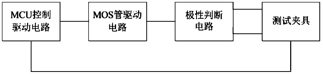
[0032] A test system applied to LED lamp test fixtures, such as figure 1 As shown, including: MCU control drive circuit, MOS tube drive circuit, polarity judgment circuit, test fixture;

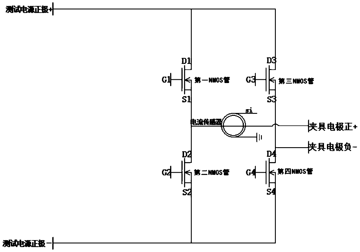
[0033] Such as Figure 2-4 As shown, the MOS transistor driving circuit is an H bridge circuit including a first NMOS transistor, a second NMOS transistor, a third NMOS transistor and a fourth NMOS transistor, the drain D1 of the first NMOS transistor, the drain of the third NMOS transistor The drain D3 is used as the positive power supply terminal of the H bridge, the source S1 of the first NMOS transistor is electrically connected to the drain D2 of the second NMOS transistor, the source S3 of the third NMOS transistor is connected to the drain of the fourth NMOS transistor Pole D4 is electrically connected, and the source S2 of the second NMOS tube and the source S4 of the fourth NMOS tube are used as the negative terminal of the power supply of the H bridge; the positive terminal of the ...

Embodiment 2

[0044] This embodiment 2 is a method for testing LED lamps based on the test system provided in embodiment 1, such as Figure 5 As shown, the specific steps are as follows:

[0045] S1. When the LED lamp to be tested is installed on the test fixture, the signals output by the single-chip microcomputers G1', G4' are low-level drive signals, and the signals output by the single-chip microcomputers G2', G3' are high-level drive signals;

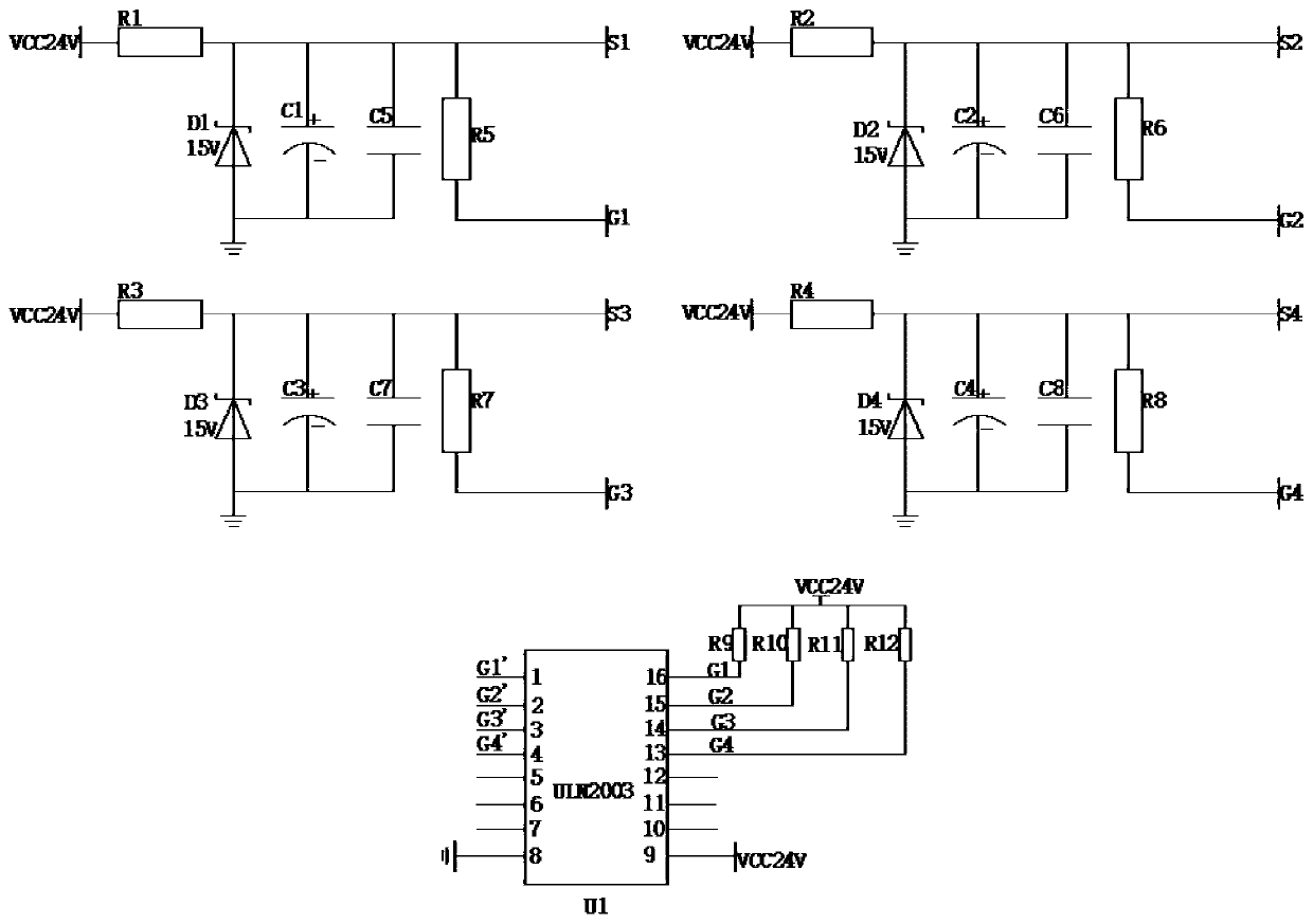
[0046] S2. After the driving signal output by the single-chip microcomputer is reversed by the ULN2003 Darlington tube and the driving capability is enhanced, it directly drives the first MOS tube and the fourth NMOS tube to turn on, and the second MOS tube and the third NMOS tube remain off; therefore, the LED lights The test current flows in from the positive pole of the test fixture and flows out from the negative pole;

[0047] S3. The current sensor Si detects the current value of the test loop, and judges whether the current value is grea...


PUM


Abstract

The invention discloses a test system applied to an LED lamp test fixture. The test system comprises an MCU control drive circuit, an MOS tube drive circuit, a polarity judgment circuit and a test fixture; the MCU control drive circuit is used for controlling the on or off state of four MOS tube of the MOS tube drive circuit, so that the direction of current flowing into the test fixture is changed, wherein the polarity judgment circuit is used for performing sampling detection and judging whether the current value of a current test loop is normal, so that whether the polarity of an LED lamp to be tested loaded on the test fixture is correct or not is judged, and a signal is fed back to the MCU control drive circuit so as to maintain or change the direction of current flowing into the test fixture currently so as to complete subsequent LED lamp test work. The test system solves the problem, that the LED lamp is low in test work efficiency and insufficient in reliability due to unilateral conductivity, of an existing LED lamp test fixture.

Description

technical field [0001] The invention relates to the technical field of LED lamp testing, in particular to a testing system applied to LED lamp testing fixtures. Background technique [0002] At present, the LED lamp test fixtures on the market have unidirectional conductivity, that is, the direction of applying current to the LED lamp must be fixed, and the LED lamp to be tested must be loaded on the fixture with the correct polarity to be able to test normally. When the electrode placement direction of the LED lamp is reversed, the tester must confirm and reload the LED lamp before continuing to complete the test of the LED lamp, which increases the workload of the test, leads to low test efficiency, and affects the reliability of the test. Contents of the invention [0003] The present invention provides a test system applied to the LED lamp test fixture to solve the problems of low test work efficiency and insufficient reliability of the LED lamp due to only one-way con...

Claims


Application Information

Patent Timeline
IPC IPC(8): H05B33/08H05B44/00
CPCH05B45/50Y02B20/30
Inventor 李茂隆
Owner 广州市微生物研究所
Why Eureka
Try Eureka