Injection device and injection method

A technology of injection device and injection agent, which is applied in the direction of injection device, injection device, liquid injection device, etc., and can solve the problems that injection agent is difficult to enter and objects suck air bubbles, etc.

Active Publication Date: 2019-09-20
MITSUBISHI ELECTRIC CORP
View PDF6 Cites 2 Cited by
  • Summary
  • Abstract
  • Description
  • Claims
  • Application Information

AI Technical Summary

Problems solved by technology

[0004] However, when the injection nozzle is vibrated in only one direction, it is difficult for the injection agent to enter the corners of the object or the four corners of the box-shaped object, and there is a problem that air bubbles are sucked into the object after injection.

Method used


Image

  • Injection device and injection method
  • Injection device and injection method
  • Injection device and injection method

Examples


Embodiment approach 1

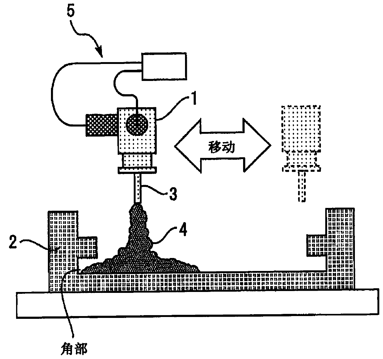
[0018] figure 1 It is a sectional view showing the injection device according to Embodiment 1. The injection nozzle 1 is arranged above the target device 2 , and injects the injection agent 4 discharged from the nozzle head 3 into the target device 2 . When the injection agent 4 is injected, the vibration generator 5 vibrates the injection nozzle 1 in multiple directions. For example, the frequency of the vibration of the injection nozzle 1 is less than or equal to 1000 Hz, and the amplitude is less than or equal to 1 mm.

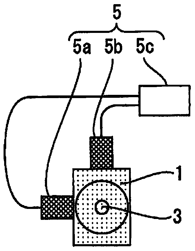
[0019] figure 2 It is a bottom view showing the injection nozzle according to the first embodiment. The vibration generating device 5 includes a plurality of vibration generators 5a, 5b provided at a plurality of places on the side of the injection nozzle 1, and an amplifier 5c that drives the vibration generators 5a, 5b. Here, two vibration generators 5a, 5b are installed on the side surfaces of the injection nozzle 1, and the injection nozzle 1 vibra...

Embodiment approach 2

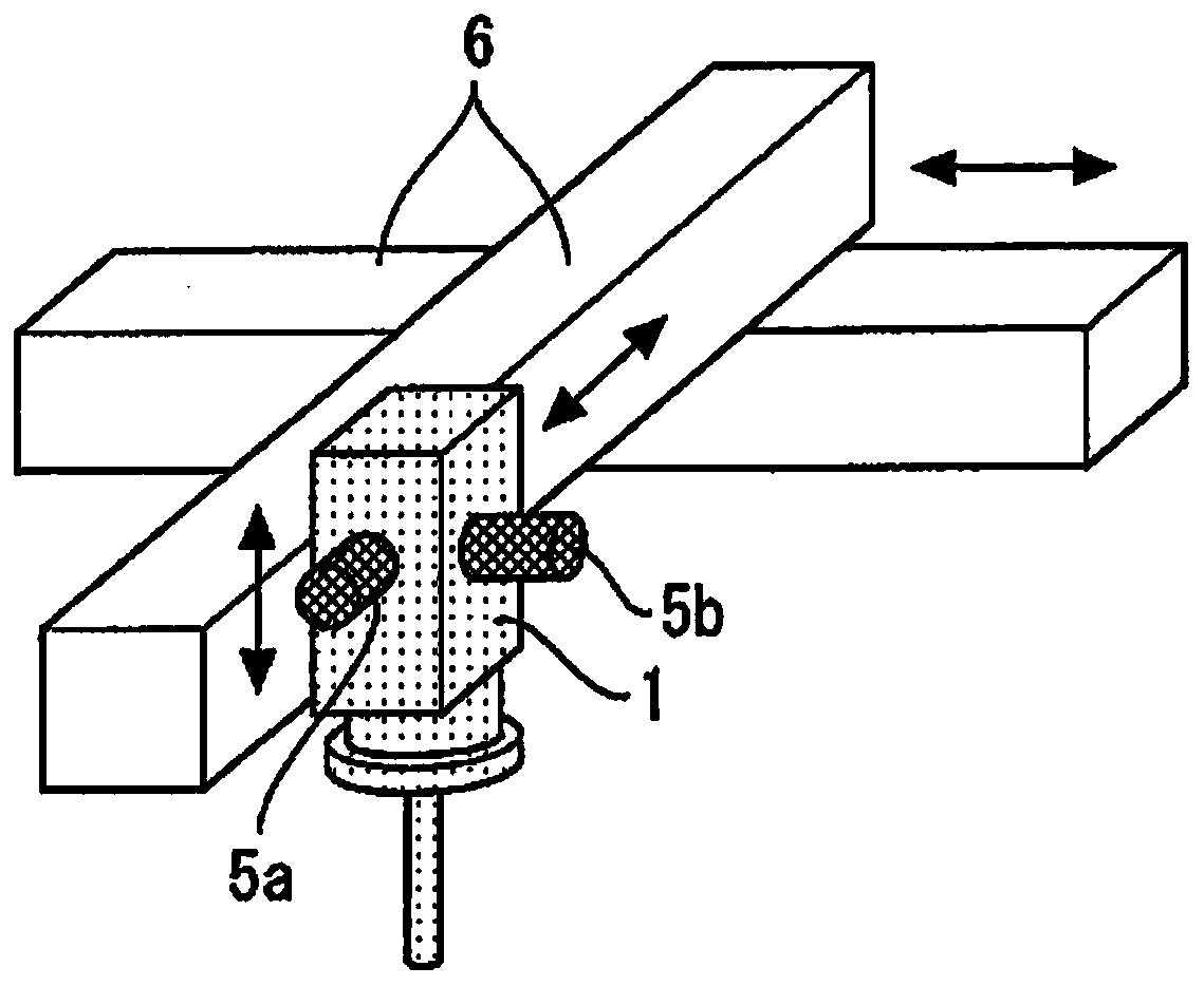
[0025] Figure 5 It is a perspective view showing the injection device according to Embodiment 2. The two injection nozzles 1 are arranged side by side on the orthogonal axis 6 . In addition, the number of injection nozzles may also be greater than or equal to three. A plurality of vibration generators 5a, 5b are provided in each of the plurality of injection nozzles 1 . By ejecting the injection agent 4 from the plurality of injection nozzles 1 at the same time, it is possible to inject a large amount of the injection agent 4 at once.


PUM


Abstract

The present invention provides an injection device and an injection method capable of shortening the injection time and suppressing the suction of bubbles. An injection nozzle (1) injects an injection agent (4) into an object (2). When the injection agent (4) is injected, a vibration generating device (5) causes the injection nozzle (1) to vibrate in a plurality of directions.

Description

technical field [0001] The present invention relates to an injection device and an injection method for injecting an injection agent into an object device. Background technique [0002] When a large amount of liquid injection agent is injected into the target object, it takes time to expand the injection material in the target object, and thus the injection time becomes longer. Also, depending on the internal structure of the container, large air bubbles may remain in the container after injection. In particular, high-viscosity injectables have poor fluidity, so their expansion is slow, and inhalation of air bubbles often occurs. In response to this, a technique of vibrating the injection nozzle in one direction when injecting the injection agent has been proposed (for example, refer to Patent Document 1). [0003] Patent Document 1: Japanese Patent Application Laid-Open No. 1-284364 [0004] However, when the injection nozzle is vibrated in only one direction, it is diff...

Claims


Application Information

Patent Timeline
Patent Type & Authority Applications(China)
IPC IPC(8): H01L21/67H01L21/56
CPCH01L21/67126H01L21/56B05B1/28B65B3/04B65B3/18H01L21/6715H01L21/67121B05B17/0623B05B17/0646B05B7/1418B05B1/16
Inventor 前田浩明
Owner MITSUBISHI ELECTRIC CORP
Why Eureka
Try Eureka