A Construction Technology of Immersed Tube Compaction Pile Using Built-in Tamper for Bottom Ramming

A construction process and technology of compacting piles, which are applied in sheet pile walls, soil protection, infrastructure engineering and other directions, and can solve the problems of small hole diameter, complex construction process and shallow treatment depth.

Inactive Publication Date: 2020-10-20
鑫润建设工程有限公司
View PDF10 Cites 0 Cited by
  • Summary
  • Abstract
  • Description
  • Claims
  • Application Information

AI Technical Summary

Problems solved by technology

[0009] In order to overcome the deficiencies of the prior art, the present invention provides a construction technique for sinking tube compaction piles using a built-in rammer for bottom ramming, which solves the problems of high engineering cost, complicated construction process, and Problems such as limited weight, shallow processing depth, and small hole diameter

Method used


Image

  • A Construction Technology of Immersed Tube Compaction Pile Using Built-in Tamper for Bottom Ramming
  • A Construction Technology of Immersed Tube Compaction Pile Using Built-in Tamper for Bottom Ramming
  • A Construction Technology of Immersed Tube Compaction Pile Using Built-in Tamper for Bottom Ramming

Examples


Embodiment 1

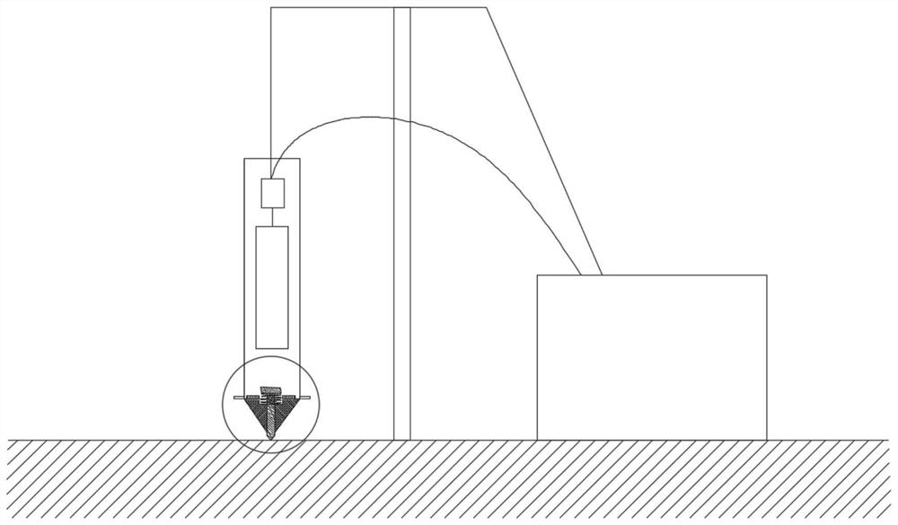
[0040] refer to figure 1 , the present embodiment 1 provides a construction technique for sinking tube compaction piles using a built-in rammer for bottom tamping, which utilizes construction equipment for construction, and the construction equipment includes a pile pipe 1 and a pile point 2 at the bottom thereof, and also includes hydraulic pressure Pile driver and the replacement structure 5 at the inner bottom of the pile pipe 1. The hydraulic pile driver 1 is an existing equipment, which mainly includes a main engine 8, a hydraulic pipeline 7, a support frame 6 and a hydraulic hammer 4 in the pile pipe. The construction process includes the following steps:

[0041] Step 1, measure the specific pile position, and place the pile tube with the pile point at the bottom at the corresponding pile position;

[0042] Step 2, using the built-in hammer to ram the inner bottom of the pile pipe, the pile tip sinks under force, and then drives the pile pipe to sink;

[0043] Step 3....

Embodiment 2

[0058] The location of the implementation project is located in a loess area in the central and western regions. The pre-constructed buildings are 30-storey residential buildings. The self-weight collapsible Class III site has a collapsible loess layer thickness of 32m.

[0059] In order to eliminate all the collapsibility in the foundation, it is required that the length of the compaction pile is 32m, the diameter of the hole is 600mm, the diameter of the pile is 800mm, and the weight of the pile hammer is 12t.

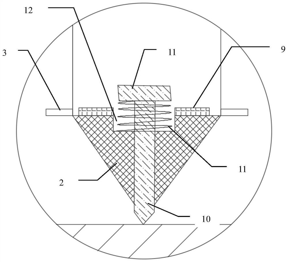
[0060] refer to figure 2 and image 3 , this embodiment 2 provides a construction process for super-long and large-diameter immersed tube compaction piles in collapsible loess areas using a built-in rammer for bottom tamping. It uses immersed tube equipment for construction, and the immersed tube equipment is the same as that of the embodiment 1. The difference is that its replacement structure includes replacement ring 9, replacement nail 10 and nail cap 11. A cir...


PUM


Abstract

The invention provides a tube sinking compacted pile construction technology using a built-in rammer for bottom ramming. The tube sinking compacted pile construction technology includes the steps that the specific pile position is determined, and a pile tube with a pile tip at the bottom is placed at the corresponding pile position; the built-in hydraulic hammer is used for ramming the bottom of the pile tube, and the pile tip is forced to sink and then drives the pile tube to sink; step 3, the pile tube is pulled out in time after sinking into the designed depth; step 4, after the pile tube is fully pulled out, a certain height of filler is added to a pile hole, and then the filler in the hole is compacted by the hydraulic hammer, and then the next layer of the filler is added and compacted, the step is repeated until the pile formation of a compacted pile is completed. According to the tube sinking compacted pile construction technology, the soil porosity can be significantly reduced, and the compressive modulus of soil is increased; the tube sinking compacted pile construction technology has the advantages of deep hole-forming depth, large hole-forming diameter, good compaction effect, low construction noise, low filling requirements, significantly reducing the project cost and the like; and a treated foundation has high bearing capacity, small settlement and differential settlement.

Description

technical field [0001] The invention belongs to the field of building construction, and in particular relates to a construction technique for sinking tube compaction piles using a built-in rammer for bottom tamping. Background technique [0002] Collapsible loess, soft soil around coastal plains, deltas, and lake basins, and underconsolidated soil foundations caused by artificial or natural geological conditions are widely distributed in my country. These foundations have the characteristics of large porosity, high compressibility, and low bearing capacity. If buildings (structures) are directly built in this area, the foundation will undergo large overall settlement or differential settlement, which will affect normal use. [0003] In addition, with the acceleration of my country's urbanization process, people's requirements for quality of life are gradually improving, and more and more high-rise and super high-rise buildings are also appearing, which puts forward higher re...

Claims


Application Information

Patent Timeline
Patent Type & Authority Patents(China)
IPC IPC(8): E02D3/08E02D5/66
CPCE02D3/08E02D5/665
Inventor 曲帅武曲帅元崔富强彭东列曹彦飞吕龙波
Owner 鑫润建设工程有限公司
Why Eureka
Try Eureka