River bed water intake structure for hydropower station forward water taking

A technology for water intakes and hydropower stations, applied in hydropower stations, hydropower, hydraulic engineering, etc., can solve the problems of sediment deposition, affecting the safety of water diversion channels and downstream turbines, and it is difficult to discharge the sand sluice, so as to reduce sedimentation , Guarantee smooth flow and reduce operating costs

Pending Publication Date: 2019-09-20
POWERCHINA CHENGDU ENG
View PDF0 Cites 0 Cited by
  • Summary
  • Abstract
  • Description
  • Claims
  • Application Information

AI Technical Summary

Problems solved by technology

Of course, there are many problems in this structure, and the main problems are as follows: 1. When the hydropower station is in normal operation, that is, when the water intake is opened, the sand flushing gate is closed, and the flood gate is closed, because the water flow enters the water intake from the river, the water flow will The flow direction has not changed, and the sediment entrained in the water flow can easily approach the water intake with the water flow, and gradually deposit in the river bed upstream of the bottom plate of the water intake. When the sediment elevation exceeds the top elevation of the bottom plate of the water intake, It is easy to enter the water intake channel through the water intake, thereby affecting the safety of the water intake channel and downstream turbines; 2. When the hydropower station floods, that is, when the water intake is closed, the sand flushing gate is closed, and the flood gate is opened, a large amount of sediment in the upstream reservoir passes through When the flood gate is discharged downstream, a small amount of sediment will also be deposited upstream of the water intake; 3. When the hydropower station flushes sand, that is, when the water intake is closed, the sand flushing gate is opened, and the flood gate is closed, although the sediment in front of the water intake The sediment is very close to the flushing sluice, but because its location is close to the bottom plate of the water intake, it is outside the influence of the discharge flow of the flushing sluice, so it is difficult to discharge through the sand flushing sluice

Method used


Image

  • River bed water intake structure for hydropower station forward water taking
  • River bed water intake structure for hydropower station forward water taking
  • River bed water intake structure for hydropower station forward water taking

Examples


Embodiment Construction

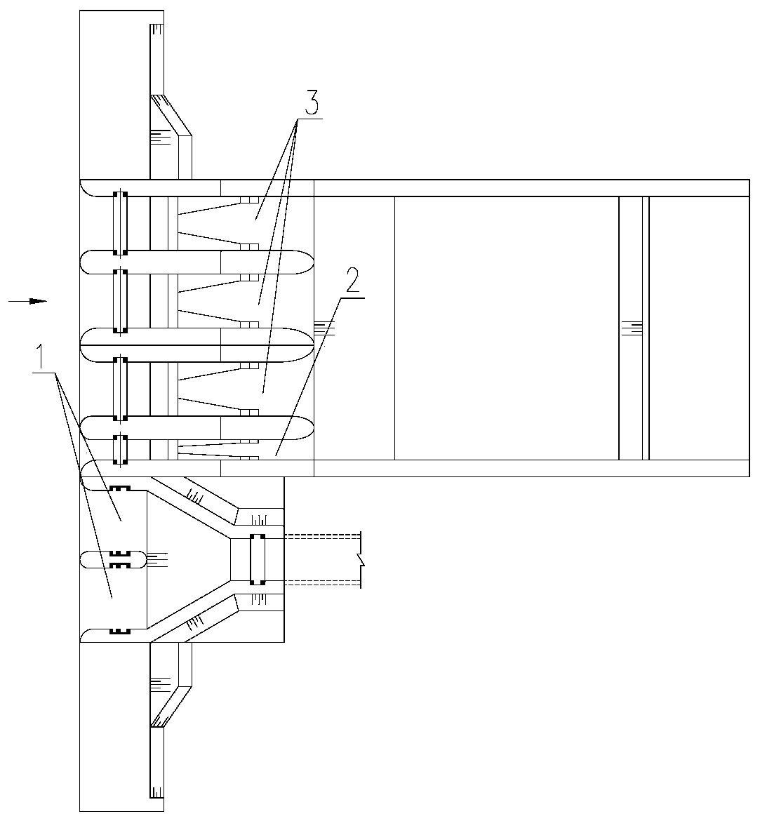
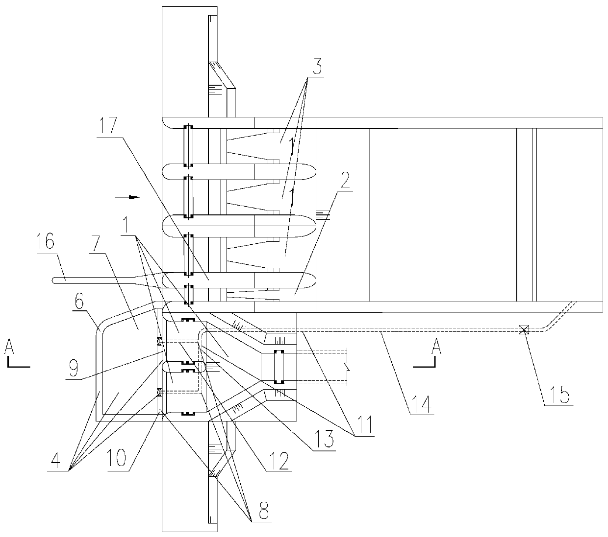
[0020] Such as figure 2 , image 3 Shown is a riverbed water intake structure for forward water intake of hydropower stations that can effectively solve the problem of river sediment deposition on the upstream side of the water intake provided by the present invention. The river bed water intake structure includes a water intake 1, a sand flushing gate 2 and a flood discharge gate 3 arranged in sequence along the width direction of the river, and the axis 3 of the water intake 1 is connected to the axis of the sand flushing gate 2 and the flood discharge gate 3 3 to be consistent, the structure of the river bed water intake also includes a pre-sand-blocking settlement discharge system 4, and the pre-sand-blocking settlement discharge system 4 is arranged in the riverbed on the upstream side of the water intake 1 and enters the water intake 1 The preceding water flow removes the large-grained sand and stones therein through the described pre-sand-blocking settlement discharge...


PUM


Abstract

The invention discloses a river bed water intake structure, particularly discloses a river bed water intake structure for hydropower station forward water taking, and belongs to the technical field of design and construction of hydraulic structures. The problem of sediment deposition on a river channel on the upstream side of a water intake can be effectively solved. The river bed water intake structure includes a water intake, a scouring sluice and a spillway sluice which are arranged sequentially in the width direction of the river channel, wherein the axis of the water intake is consistent with the axes of the scouring sluice and the spillway sluice; and the river bed water intake structure further comprises a front sand blocking sedimentation discharge system, the front sand blocking sedimentation discharge system is arranged in a river bed on the upstream side of the water intake, and large-particle sandstone in water flow before entering the water intake is cleared away through the front sand blocking sedimentation discharge system.

Description

technical field [0001] The invention relates to a river bed water intake structure, in particular to a river bed water intake structure used for forward water intake of a hydropower station, and belongs to the technical field of design and construction of hydraulic structures. Background technique [0002] In order to prevent the sand-laden water flow in the river from directly entering the water intake and causing damage to the water diversion channel and the turbine unit, most hydropower projects adopt the lateral arrangement of the water intake, that is, the arrangement in which the axis of the water intake intersects the flow direction of the river at a small angle. However, for hydropower projects with open river valleys and gentle terrain on both sides, in order to simplify the building layout and save engineering work, it is often necessary to adopt the positive layout of the water intake, such as figure 1 shown. The structural features of this type of positive arran...

Claims


Application Information

Patent Timeline
IPC IPC(8): E02B9/04E02B5/08
CPCE02B5/085E02B9/04Y02E10/20
Inventor 张公平唐忠敏商开卫
Owner POWERCHINA CHENGDU ENG
Why Eureka
Try Eureka