Novel sparrow-pecking moxibustion apparatus
A sparrow pecking moxibustion, a new type of technology, applied in the field of sparrow pecking moxibustion instrument, can solve the problem of manpower occupation and achieve the effect of avoiding burns, good use effect, amplitude and line standard
- Summary
- Abstract
- Description
- Claims
- Application Information
AI Technical Summary
Problems solved by technology
Method used
Image
Examples
Embodiment 1
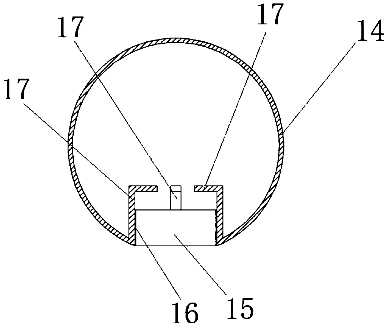
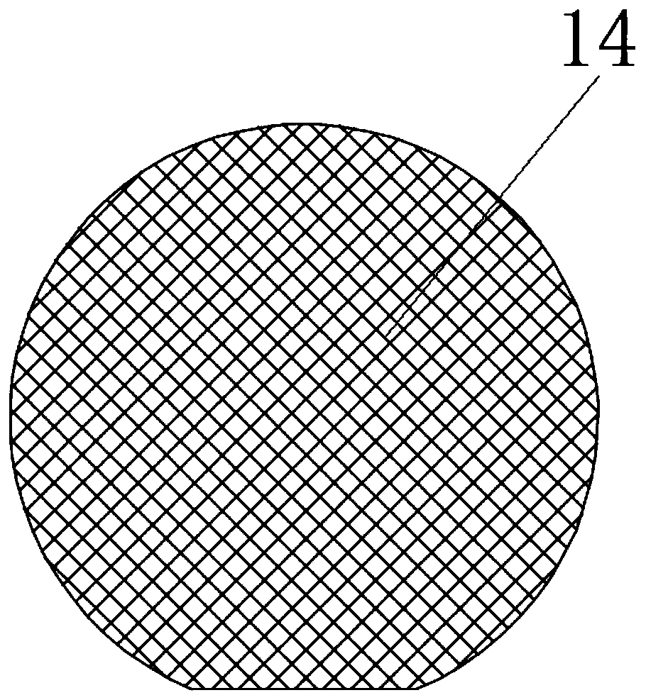
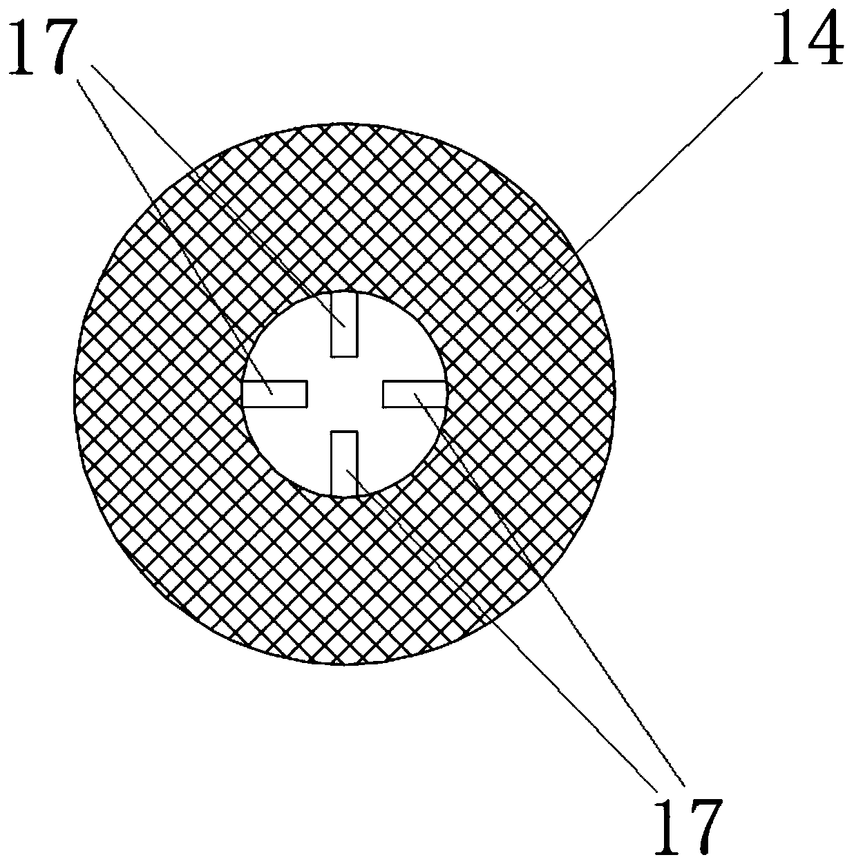
[0032] A new type of sparrow pecking moxibustion instrument, such as Figure 1-8 As shown, it includes a base 1, a bracket 2, a linear reciprocating motor 3, a moving plate 4, a protrusion 5, a screw hole 6, a cylinder 7, a screw 8, a cavity 9, a spring 10, a moxibustion strip 11, and a burning point 12. External threaded part 13, mesh cover 14, pipe body 15, internal threaded part 16, corner strip 17, wherein, the bracket 2 is fixedly connected to the base 1, the outer wall of the linear reciprocating motor 3 is fixedly connected to the bracket 2, and the linear reciprocating The motion shaft of the motor 3 is connected with the protrusion 5 on the upper end of the motion plate 4, and there are several screw holes 6 at the lower end of the motion plate 4; A screw rod 8 is fixedly connected to the outside of the end surface, and the inside of the cylinder 7 is a cavity 9, and the spring 10 is located in the cavity 9. One end of the spring 10 is fixedly connected to the inside ...
Embodiment 2
[0102] A new type of sparrow pecking moxibustion instrument, such as Figure 1-8 As shown, it includes a base 1, a bracket 2, a linear reciprocating motor 3, a moving plate 4, a protrusion 5, a screw hole 6, a cylinder 7, a screw 8, a cavity 9, a spring 10, a moxibustion strip 11, and a burning point 12. External threaded part 13, mesh cover 14, pipe body 15, internal threaded part 16, corner strip 17, wherein, the bracket 2 is fixedly connected to the base 1, the outer wall of the linear reciprocating motor 3 is fixedly connected to the bracket 2, and the linear reciprocating The motion shaft of the motor 3 is connected with the protrusion 5 on the upper end of the motion plate 4, and there are several screw holes 6 at the lower end of the motion plate 4; A screw rod 8 is fixedly connected to the outside of the end surface, and the inside of the cylinder 7 is a cavity 9, and the spring 10 is located in the cavity 9. One end of the spring 10 is fixedly connected to the inside ...
PUM
 Abstract
Description
Claims
Application Information
 - R&D Engineer
- R&D Manager
- IP Professional
- Industry Leading Data Capabilities
- Powerful AI technology
- Patent DNA Extraction
Browse by: Latest US Patents, China's latest patents, Technical Efficacy Thesaurus, Application Domain, Technology Topic, Popular Technical Reports.
© 2024 PatSnap. All rights reserved.Legal|Privacy policy|Modern Slavery Act Transparency Statement|Sitemap|About US| Contact US: help@patsnap.com


