A pressure cooking appliance with directional pressure relief
A cooking utensil and pressure technology, applied in pressure cookers, cooking utensils, kitchen utensils, etc., can solve the problems of scalding users and random pressure relief positions, and achieve the effects of avoiding scalding, facilitating manufacturing, and improving safety.
- Summary
- Abstract
- Description
- Claims
- Application Information
AI Technical Summary
Problems solved by technology
Method used
Image

Examples
Embodiment 1
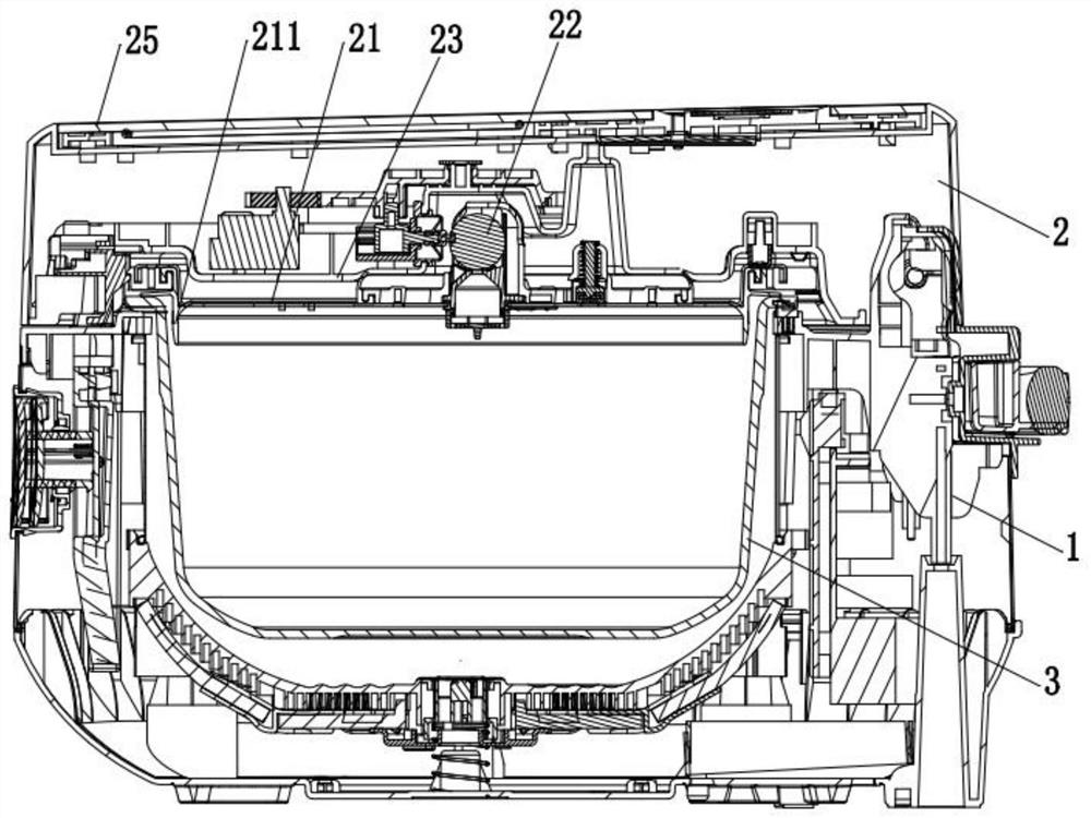
[0041] Such as figure 1 As mentioned above, the pressure cooking appliance in this embodiment includes a pot body 1 and a pot cover 2, the pot body 1 is provided with an inner container 3, and the pot cover 2 includes an inner cover 21, and the inner cover 21 is sealed with the inner container 3 A pressure cooking cavity is formed, and the pot cover 2 of the present embodiment is also provided with a pressure ball valve 22, through which the pressure of the cooking cavity is controlled. In order to form a sealed environment, the inner cover 21 is provided with a sealing ring 211 , and when the inner cover 21 is closed to the inner container 3 , the sealing ring 211 seals the gap between the inner cover 21 and the inner container 3 .
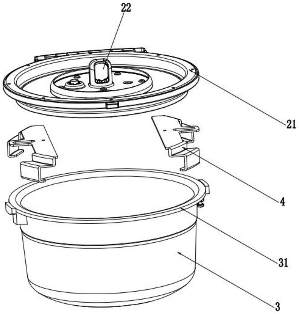
[0042] Can refer to Figure 2-Figure 6 , the pot cover 2 also includes a clamp 4, which can ensure that the inner cover 21 is covered on the inner tank 3 by the clamp 4, and the inner cover 21 will not be far away from the inner tank 3 when pres...
Embodiment 2
[0050] This embodiment is further improved on the basis of Embodiment 1. In this embodiment, the inner cover 21 is provided with a sealing ring 211, and the sealing ring 211 is provided with a weak portion 212. The weak portion 212 Located in the circumferential gap between the rear clamps in the circumferential direction of the inner cover. The sealing ring 211 is provided with a weak portion 212 , and when the sealing ring is installed, the weak portion 212 is located in the circumferential gap between the rear clamps in the circumferential direction of the inner cover. Therefore, when the pressure is increased abnormally, the weak part of the sealing ring is easier to turn out to release the pressure, and the weak part is located in the non-locking area of the rear, so as to ensure the directional pressure release from the rear and further improve the safety of use. The weak part can be understood as the lower strength of the sealing ring, such as the lower strength of th...
Embodiment 3
[0053] The difference between this embodiment and Embodiment 1 is that in this embodiment, the locking strength of the rear clamp is smaller than that of the front clamp. When an abnormal situation occurs, the rear clamp is more likely to be damaged due to the weak locking strength of the rear, so that directional pressure relief to the rear can also be realized.
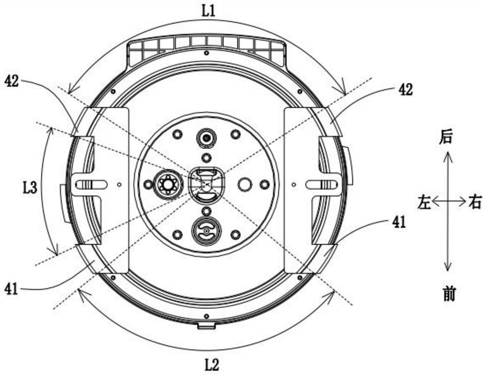
[0054] can refer to Figure 8 , the locking area of the rear clamp 42 in this embodiment is smaller than the locking area of the front clamp 41, because the locking area of the rear clamp 42 is too small, so the locking strength of the rear is weak, Therefore, when an abnormal situation occurs, the rear clamp 42 is more easily deformed and damaged, so as to achieve pressure release from the rear. Can refer to Figure 7 , the width of the rear clamp 42 in the vertical direction is A, the width of the front clamp 41 in the vertical direction is B, and A is smaller than B, so the locking area of the rear clam...
PUM
 Abstract
Description
Claims
Application Information
 - R&D
- Intellectual Property
- Life Sciences
- Materials
- Tech Scout
- Unparalleled Data Quality
- Higher Quality Content
- 60% Fewer Hallucinations
Browse by: Latest US Patents, China's latest patents, Technical Efficacy Thesaurus, Application Domain, Technology Topic, Popular Technical Reports.
© 2025 PatSnap. All rights reserved.Legal|Privacy policy|Modern Slavery Act Transparency Statement|Sitemap|About US| Contact US: help@patsnap.com