
Contactless voltage stabilizer main circuit with high voltage stabilization precision and contactless voltage stabilizer

A voltage-stabilizing precision, non-contact technology, applied in circuits, transformers, variable transformers, etc., can solve problems such as taps that are difficult to handle, and achieve the effects of simplifying the manufacturing process, enhancing reliability and working life, and stabilizing voltage in a wide range

Pending Publication Date: 2019-09-17
PEARL ELECTRIC +1
View PDF0 Cites 4 Cited by
  • Summary
  • Abstract
  • Description
  • Claims
  • Application Information

AI Technical Summary

Problems solved by technology

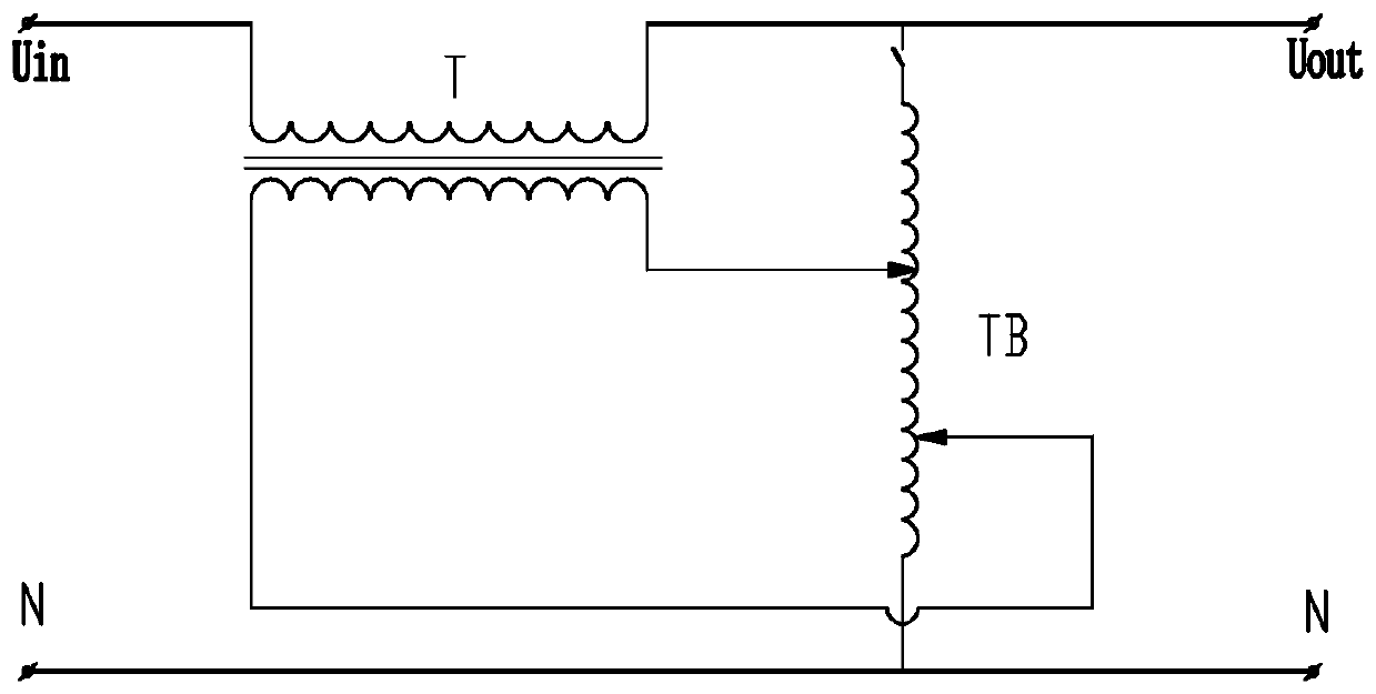
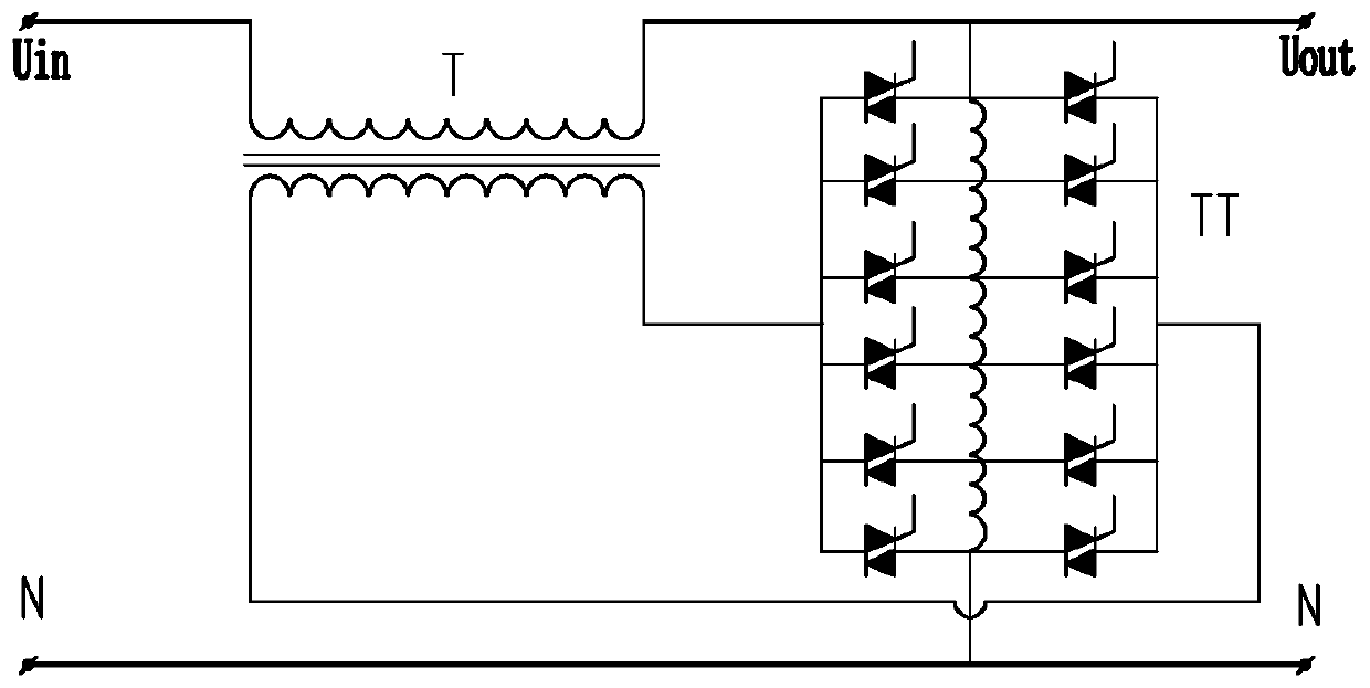
However, if this method is to improve the voltage stabilization range and accuracy, a large number of taps need to be set on the autotransformer, and each tap needs to be connected to multiple thyristor switches at the same time. In the process of making the voltage stabilizer, the taps are difficult to handle. , so this method is only suitable for places that do not require high precision of voltage regulation

Method used


Image

  • Contactless voltage stabilizer main circuit with high voltage stabilization precision and contactless voltage stabilizer
  • Contactless voltage stabilizer main circuit with high voltage stabilization precision and contactless voltage stabilizer
  • Contactless voltage stabilizer main circuit with high voltage stabilization precision and contactless voltage stabilizer

Examples


Embodiment Construction

[0026] The present invention is further described below in conjunction with embodiment.

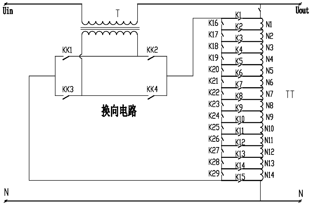
[0027] Such as image 3 Shown is the main circuit of the non-contact voltage stabilizer with high voltage stabilization accuracy of this embodiment, which includes a compensation transformer T, an autotransformer TT, a commutation circuit, a first contactor switch K1-K15 and a second contactor switch K16-K29. The autotransformer TT is provided with two lead-out terminals located at both ends and n taps between the two lead-out terminals. The two lead-out terminals are respectively connected to the two ends of the main coil of the autotransformer TT. The two lead-out terminals and n taps They are respectively connected to a parallel wire in parallel through the first contactor switch K1-K15, and a second contactor switch K16-K29 is provided between every two adjacent connection points on the parallel wire, and the two ends of the parallel wire The commutation circuit is connected with th...


PUM


Abstract

The invention discloses a contactless voltage stabilizer main circuit with high voltage stabilization precision. The contactless voltage stabilizer main circuit comprises a compensation transformer, an autotransformer and a reversing circuit. The two lead-out terminals and the n taps of the autotransformer are connected in parallel to be connected with a parallel wire through first contactor switches. Second contactor switches are arranged between every two adjacent connection points on the parallel wire. Both ends of the parallel wire are connected to the primary winding of the compensation transformer through the reversing circuit. The contactless voltage stabilizer main circuit has high voltage stabilization precision and a wide voltage stabilization range. The invention also discloses a contactless voltage stabilizer, which comprises a contactless voltage stabilizer main circuit, an output sampling circuit, a comparator and a control circuit, wherein the output sampling circuit acquires the voltage at the output end of a circuit to be subjected to voltage stabilization; the comparator is connected to the output sampling circuit; the control circuit is connected to the comparator, the reversing circuit, the first contactor switches and the second contactor switches. The contactless voltage stabilizer achieves high precision and voltage stabilization in a wide range.

Description

technical field [0001] The present invention relates to a main circuit of a non-contact voltage stabilizer with high voltage stabilizing precision, and also relates to a non-contact voltage stabilizer utilizing the main circuit of the non-contact voltage stabilizer with high voltage stabilizing precision to realize voltage stabilization. Background technique [0002] The voltage stabilizer mainly transforms the input voltage within a certain range into the output voltage within the required precision range through the voltage stabilizing circuit. important parameters of the compressor performance. [0003] Traditional mechanically compensated regulators such as figure 1 As shown, the carbon brush on the voltage regulator TB slides on the surface of the voltage regulator coil mainly by the positive and negative rotation of the servo motor, thereby changing the compensation voltage of the compensation transformer T, and its voltage regulation is basically linear. However, du...

Claims


Application Information

Patent Timeline
Patent Type & Authority Applications(China)
IPC IPC(8): H02M5/12H01F29/02
CPCH02M5/12H01F29/025
Inventor 向勇黄文军禤冠星张甬韩少华蔡定国唐金权
Owner PEARL ELECTRIC
Learn More