
Liquid level monitoring system

A liquid level monitoring and liquid level control technology, applied in the control field, can solve the problems of weak signal anti-interference ability, difficult upgrade and maintenance, high cost, etc., to improve the signal anti-interference ability, avoid wiring complexity, and reduce costs.

Inactive Publication Date: 2019-09-17
LIAONING UNIVERSITY OF PETROLEUM AND CHEMICAL TECHNOLOGY
View PDF0 Cites 1 Cited by
  • Summary
  • Abstract
  • Description
  • Claims
  • Application Information

AI Technical Summary

Problems solved by technology

[0003] In view of this, the present invention provides a liquid level monitoring system, the main purpose of which is to solve the problem of traditional wired control wiring complex, weak signal anti-interference ability, high cost, difficult to upgrade and maintain, and the wireless control network consumes a lot of power and cannot be realized. Problems with mobile wireless monitoring

Method used


Image

  • Liquid level monitoring system
  • Liquid level monitoring system
  • Liquid level monitoring system

Examples


Embodiment Construction

[0032] Exemplary embodiments of the present disclosure will be described in more detail below with reference to the accompanying drawings. Although exemplary embodiments of the present disclosure are shown in the drawings, it should be understood that the present disclosure may be embodied in various forms and should not be limited by the embodiments set forth herein. Rather, these embodiments are provided for more thorough understanding of the present disclosure and to fully convey the scope of the present disclosure to those skilled in the art.

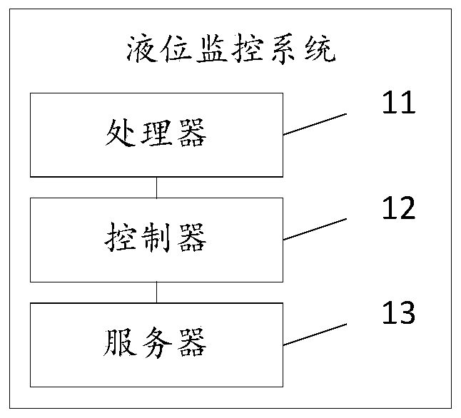
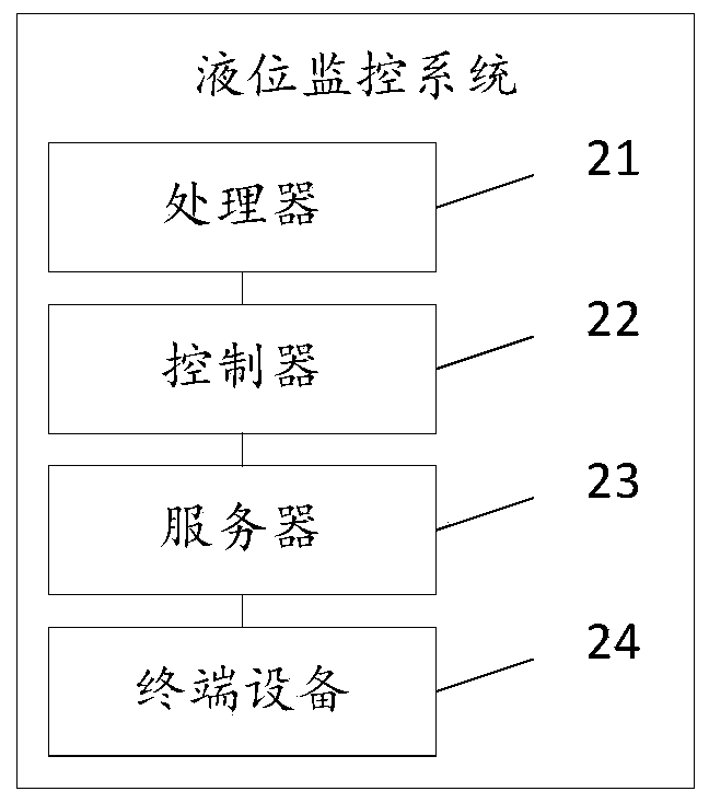
[0033] The embodiment of the present invention provides a liquid level monitoring system, such as figure 1 As shown, the system includes: a processor 11, a controller 12, a server 13,

[0034] The processor 11 is configured to send the liquid level setting value to the controller 12 by establishing the first thread in the two threads, and receive the liquid level fed back by the controller 12 by establishing the second thread in th...


PUM


Abstract

The invention discloses a liquid level monitoring system, and relates to the technical field of control. The liquid level monitoring system mainly aims to solve the problems that the traditional wired control wiring is complex, the signal anti-interference capability is weak, the cost is high, the upgrading and maintenance are difficult, the wireless control network is high in power consumption, and the wireless monitoring problem of a mobile terminal cannot be realized. The liquid level monitoring system comprises a processor, a controller and a server, wherein the processor is used for sending a liquid level setting value to the controller by establishing a first thread in double threads, and receiving a liquid level measurement value fed back by the controller by establishing a second thread in the double threads, and performing displaying; the controller is used for calculating a liquid level control parameter and outputting according to the received liquid level setting value sent by the processor by adopting a PID control algorithm, and sending the detected liquid level measurement value to the processor and the server in a wireless communication mode when the control operation of the liquid level control parameter is operated; and the server is used for storing the liquid level measurement value sent by the controller and generating historical data of the liquid level measurement value.

Description

technical field [0001] The invention relates to the technical field of control, in particular to a liquid level monitoring system. Background technique [0002] In the production process of heavy industries such as chemical industry and oil refining, liquid level monitoring has always been one of the important factors affecting production demand. At present, with the gradual development of wireless networks, the existing liquid level monitoring can be monitored through a combination of wireless control systems and digital control systems based on digital regulators, PLC, DCS and FCS. However, due to the complexity of traditional wired control wiring, Weak signal anti-interference ability, high cost, difficult to upgrade and maintain, and high power consumption of wireless control network, unable to realize wireless monitoring of mobile terminals. Therefore, a liquid level monitoring system is urgently needed to solve the above problems. Contents of the invention [0003] ...

Claims


Application Information

Patent Timeline
IPC IPC(8): G05B11/42
CPCG05B11/42
Inventor 刘云涛金鑫
Owner LIAONING UNIVERSITY OF PETROLEUM AND CHEMICAL TECHNOLOGY
Learn More