
Electromagnetic Micropump device and liquid pumping method thereof

A micro-pump and electromagnetic technology, which is applied to components, pumps, and pump control of elastic fluid pumping devices, can solve problems such as high complexity and high cost, difficult flow control, etc., achieve high response speed, low manufacturing cost, The effect of continuous and stable flow

Active Publication Date: 2019-09-17
HANGZHOU DIANZI UNIV
View PDF6 Cites 2 Cited by
  • Summary
  • Abstract
  • Description
  • Claims
  • Application Information

AI Technical Summary

Problems solved by technology

The existing micropump has a complex structure and high cost, and it is difficult to control the flow

Method used


Image

  • Electromagnetic Micropump device and liquid pumping method thereof
  • Electromagnetic Micropump device and liquid pumping method thereof
  • Electromagnetic Micropump device and liquid pumping method thereof

Examples


Embodiment Construction

[0033] The present invention will be further described below in conjunction with accompanying drawing.

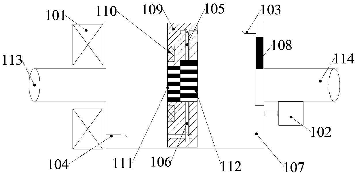
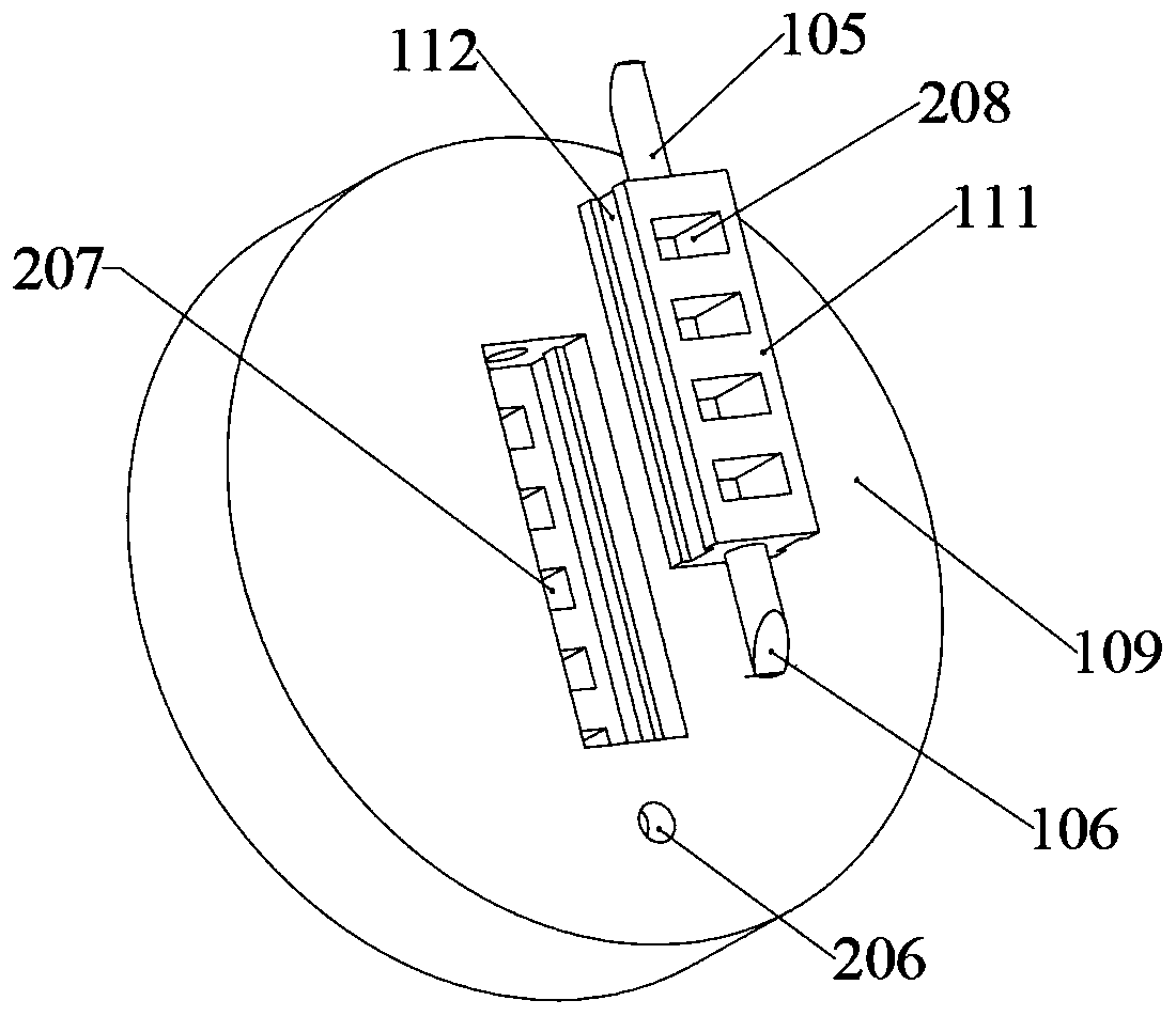
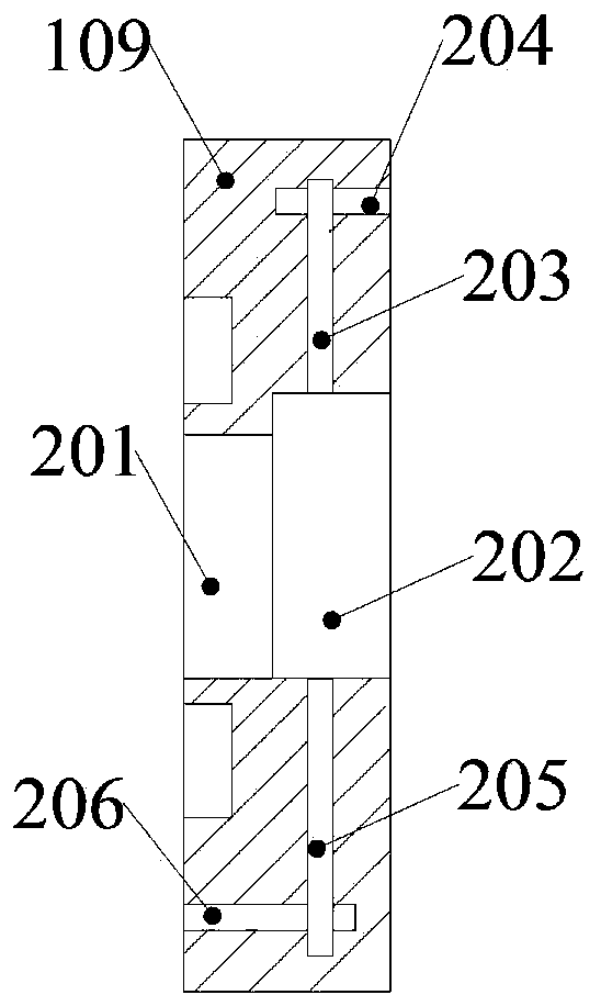
[0034] Such as figure 1 As shown, an electromagnetic micropump device includes a drive cylinder, a switching piston, a flow regulating mechanism 108 , a liquid inlet pipe 113 and a liquid outlet pipe 114 . The driving cylinder includes a cylinder body 107 , an electromagnetic coil 101 , a first wedge 103 and a second wedge 104 . Both ends of the cylinder body 107 are respectively provided with a liquid inlet and a liquid outlet. The liquid inlet of the cylinder body 107 communicates with the output port of the liquid inlet pipe 113 . The input port of the liquid inlet pipe 113 communicates with the oil tank. The liquid outlet of the cylinder 107 is connected with the input port of the liquid outlet pipe 114 through the flow regulating mechanism 108 . The electromagnetic coil 101 is wound around the end of the cylinder body 107 where the liquid inlet is opened. The elec...


PUM


Abstract

The invention discloses an electromagnetic Micropump device and a liquid pumping method thereof. An existing Micropump is complex in structure and high in cost and is difficult to control flow. The electromagnetic Micropump device comprises a driving cylinder, a switching type piston and a flow adjusting mechanism, wherein the driving cylinder comprises a cylinder body, an electromagnetic coil, a first wedge and a second wedge, the two ends of the cylinder body are correspondingly provided with a liquid inlet and a liquid outlet, the flow adjusting mechanism is arranged at the liquid outlet of the cylinder body, the electromagnetic coil is arranged at one end of the cylinder body, and the inner ends of the first wedge and the second wedge are fixed with the two ends of an inner cavity of the cylinder body correspondingly; the switching type piston comprises a first wedge rod, a second wedge rod, a piston body, a permanent magnet, a fixing block and a switching sliding block, and a fixed flow channel cavity, a movable flow channel cavity, a first transmission channel, a first wedge channel, a second transmission channel and a second wedge channel are formed in the piston body. According to the electromagnetic Micropump device and the liquid pumping method thereof, the action of the pump is controlled through the electromagnetic force period, so that the driving function is safe, the volume is small, the power consumption is low, and the response speed is high.

Description

technical field [0001] The invention belongs to the technical field of microfluidic control systems, and in particular relates to an electromagnetic micropump device and a liquid pumping method thereof. Background technique [0002] Microfluidic control systems have been applied in many fields, and there are two important devices, one is a microvalve and the other is a micropump. The microvalve mainly controls the execution of the microfluidic system, which is equivalent to the role of a switch. The micropump mainly determines the movement mode of the microfluid. Micropumps are currently being used more and more in medicine, such as drug delivery, DNA synthesis and micro fluid supply, precise control and so on. The existing micropump has a complex structure and high cost, and it is difficult to control the flow. Contents of the invention [0003] The object of the present invention is to provide an electromagnetic micropump device and a liquid pumping method thereof. ...

Claims


Application Information

Patent Timeline
Patent Type & Authority Applications(China)
IPC IPC(8): F04B17/04F04B19/00F04B53/14F04B53/16F04B49/00
CPCF04B17/04F04B19/006F04B49/00F04B53/14F04B53/162
Inventor 许明孙森陈国金
Owner HANGZHOU DIANZI UNIV
Learn More