Cantilever wheel belt polishing device with controlled pressure and polishing method

A polishing device and cantilever technology, which is applied in the direction of grinding/polishing equipment, abrasive belt grinders, optical surface grinders, etc., can solve the problems of inability to effectively polish complex surface optical elements, inability to efficiently polish workpieces, singleness, etc., and achieve improved polishing surface Shape accuracy, improve polishing accuracy, and avoid slipping

Active Publication Date: 2019-09-17
HARBIN INST OF TECH
View PDF7 Cites 6 Cited by
  • Summary
  • Abstract
  • Description
  • Claims
  • Application Information

AI Technical Summary

Problems solved by technology

[0003] In order to solve the problem that the polishing method in the prior art will introduce a certain medium and high frequency error during polishing, it will bring great difficulty to improve the surface shape accuracy, and it cannot effectively polish complex surface optical elements with a large depth-to-diameter ratio, especially the inner surface. At the same time, the controllable contact pressure polishing device mostly adopts a single contact control method, which cannot efficiently polish the workpiece with a large difference from the target surface shape, and then provides a controllable pressure cantilever wheel belt polishing device and polishing method

Method used


Image

  • Cantilever wheel belt polishing device with controlled pressure and polishing method
  • Cantilever wheel belt polishing device with controlled pressure and polishing method
  • Cantilever wheel belt polishing device with controlled pressure and polishing method

Examples


specific Embodiment approach 1

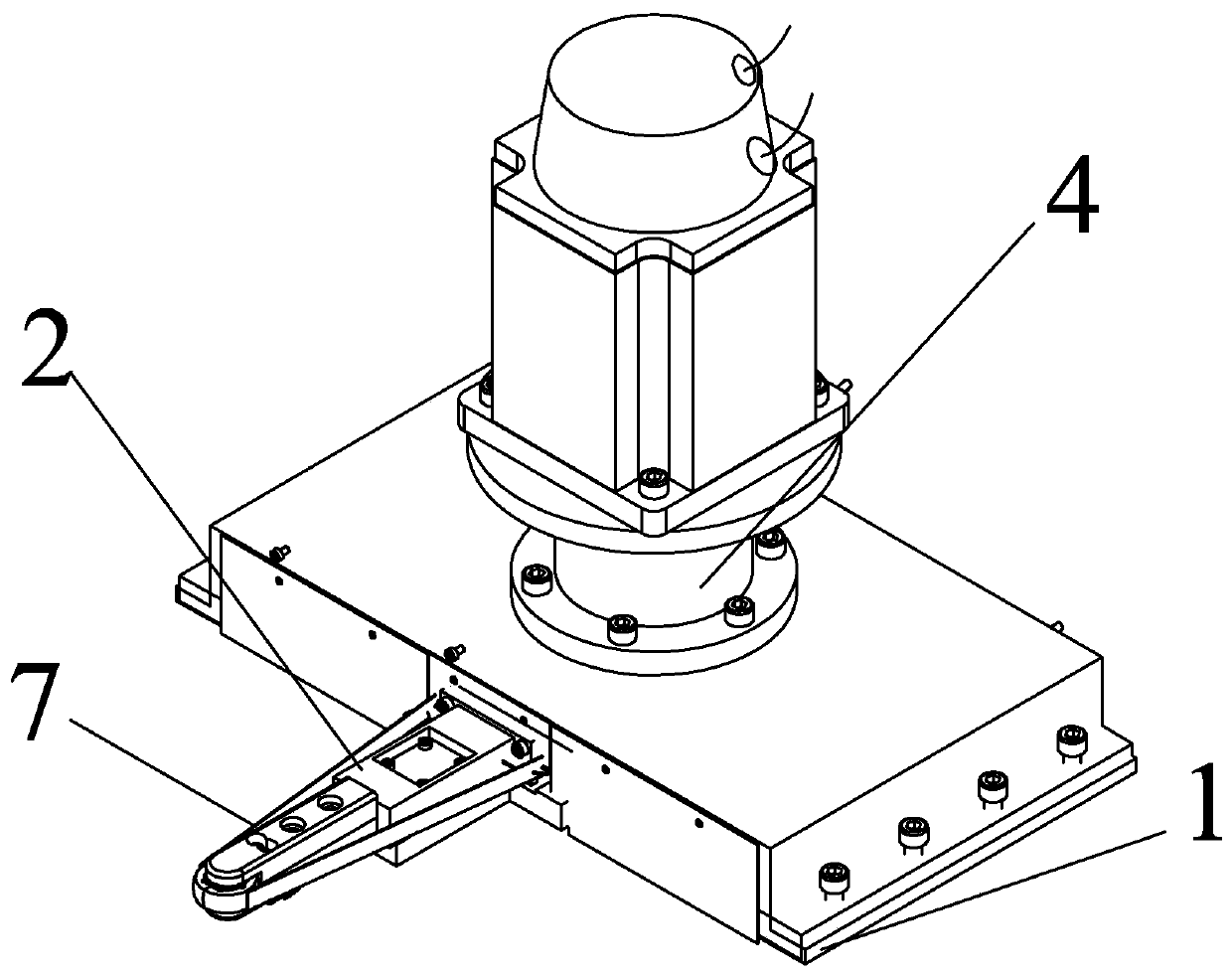
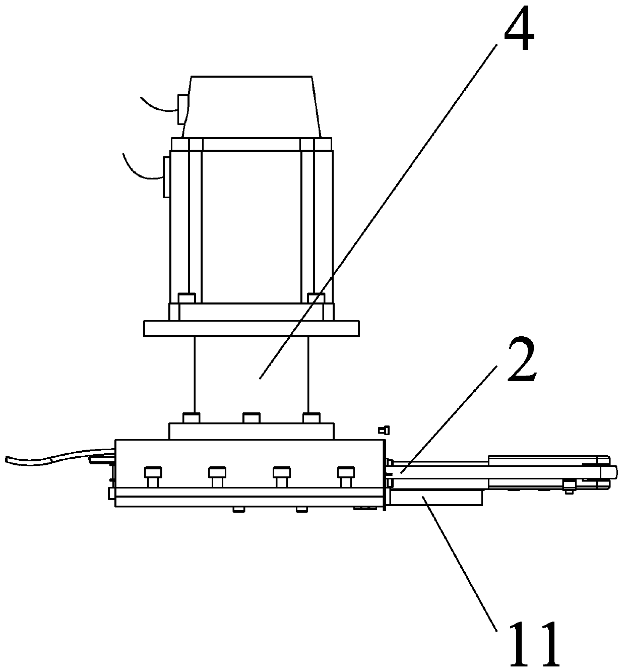
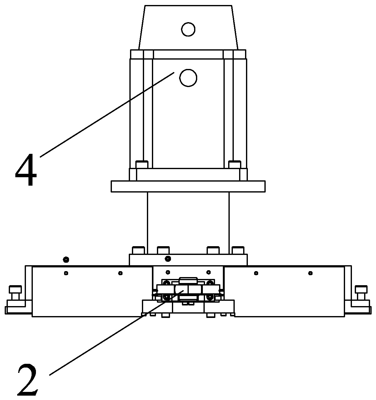
[0044] Specific implementation mode one: combine Figure 1 to Figure 3 and Figure 19 to Figure 23 Describe this embodiment, a cantilever belt polishing device with controllable pressure in this embodiment, which includes a bottom plate 1, a contact wheel cantilever wheel rod assembly 2, a motor drive assembly 4, a polishing belt trimming assembly 5, a polishing belt 7, two a cylinder tensioning assembly 3 and N waterproof guide idlers 6, where N is a positive integer;

[0045] The contact wheel cantilever wheel rod assembly 2 is installed on the upper surface of the bottom plate 1 through the cylinder body of the three-rod cylinder 25 and the guide rail base of the high-precision linear guide rail assembly 24, and the two cylinder tensioning assemblies 3 are relatively arranged on the contact wheel cantilever wheel rod The two sides of the component 2, and the tail ends of the two cylinder tensioning components 3 are set opposite to the tail ends of the trolley cantilever whee...

specific Embodiment approach 2

[0047] Specific implementation mode two: combination Figure 21 This embodiment is described. This embodiment is to further limit the base plate 1 described in the first embodiment. In this embodiment, the base plate 1 is a cuboid, and a connecting plate 11 is provided on one side of the base plate 1 . Other compositions and connection methods are the same as those in Embodiment 1.

specific Embodiment approach 3

[0048] Specific implementation mode three: combination Figure 4 to Figure 7 Describe this embodiment. This embodiment is to further limit the contact wheel cantilever wheel rod assembly 2 described in the first specific embodiment. In this embodiment, 3. The contact wheel cantilever wheel rod assembly 2 includes an integrated contact wheel 21 , high-precision linear guide rail assembly 24, three-rod cylinder 25, main support rod 26, acoustic emission sensor 27, two sealed race bearings 22 and two cantilever contact rods 23;

[0049] The high-precision linear guide rail assembly 24 includes a slider A and a high-precision linear guide rail, and the slider A is slidingly connected to the high-precision linear guide rail;

[0050] One end of the main support rod 26 is fixedly connected with the piston rod of the three-rod cylinder 25, the other end of the main support rod 26 is provided with a connecting arm, the upper surface of the main support rod 26 is provided with a groove...


PUM


Abstract

The invention provides a cantilever wheel belt polishing device with controlled pressure and a polishing method, belongs to the technical field of ultra-precision processing, and solves the problem that the polishing method in the prior art introduces a certain medium-high frequency error during polishing, so improving the surface precision is difficult, and optical components with large aspect ratio and complex surface cannot be polished effectively, specifically the inner surfaces; meanwhile, the controllable contact pressure polishing device adopts a single contact control method, which cannot effectively polish workpiece with great difference of the target surface. The polishing device provided by the invention comprises a bottom plate, a wheel bar assembly, a drive assembly, a dressing assembly, a polishing belt, a tensioning assembly and a guide idler, is mainly used for ultra-precision machining of optically complex surfaces of hard and brittle materials.

Description

technical field [0001] The invention relates to a pressure-controllable cantilever wheel belt polishing device and a polishing method, belonging to the technical field of ultra-precision processing. Background technique [0002] In the complex surface processing technology in the field of precision optical processing, it is necessary to polish the optical surface after milling to reduce the damage of the workpiece and the surface roughness of the workpiece, and improve the surface accuracy and surface quality of the workpiece to meet the actual use. Require. At present, there are many methods for polishing curved optical components, such as magnetorheological polishing, water jet polishing, airbag polishing, ion beam polishing, laser polishing, etc. Most of the existing controllable contact pressure polishing tools are sub-aperture spherical polishing heads. It has good shape modification ability, but at the same time, it will introduce certain medium and high frequency err...

Claims


Application Information

Patent Timeline
Patent Type & Authority Applications(China)
IPC IPC(8): B24B13/00B24B21/00B24B21/18B24B49/00B24B49/16B24B21/20
CPCB24B13/00B24B21/006B24B21/18B24B21/20B24B49/00B24B49/003B24B49/16
Inventor 郭兵纪云龙赵清亮
Owner HARBIN INST OF TECH
Why Eureka
Try Eureka