Effusion drainage device for cardiovascular medicine department

A cardiovascular and internal medicine technology, applied in the field of cardiovascular internal medicine effusion drainage device, can solve the problems of increasing patients' treatment pain, lack of fixed structure, sharp puncture needle, etc., and achieve the effect of being easy to promote and use, reducing pain and reducing load

Inactive Publication Date: 2019-09-17
徐卫娟
View PDF7 Cites 11 Cited by
  • Summary
  • Abstract
  • Description
  • Claims
  • Application Information

AI Technical Summary

Problems solved by technology

[0002] Common effusions in cardiovascular medicine mainly include pericardial effusion, which is common in acute pericarditis, chronic pericarditis, uremia, hypoproteinemia, tumor pericardial metastasis, traumatic pericarditis, acute myocardial infarction and other diseases. The generation of effusion will cause symptoms such as dyspnea, orthopnea, distended jugular veins, and paranormal pulse. In order to ensure the safety of the patient’s life, it is necessary to quickly extract the effusion in the pericardium, and the extraction of pericardial effusion requires drainage. Devices, such as the patent application publication code 201820243402.8, which discloses a cardiovascular medicine effusion drainage device, but there are certain defects in the use of this patent. On the one hand, the function is too single, and patients often need it during treatment. Along with infusion and other treatment, on the other hand, there is a lack of corresponding fixing structure, and the puncture needle of the drainage structure is relatively sharp. If the patient is not fixed, the patient is likely to suffer additional injuries due to his own actions, which will increase the pain of treatment for the patient.

Method used


Image

  • Effusion drainage device for cardiovascular medicine department
  • Effusion drainage device for cardiovascular medicine department
  • Effusion drainage device for cardiovascular medicine department

Examples


Embodiment Construction

[0027] The following will clearly and completely describe the technical solutions in the embodiments of the present invention with reference to the accompanying drawings in the embodiments of the present invention. Obviously, the described embodiments are only some, not all, embodiments of the present invention. Based on the embodiments of the present invention, all other embodiments obtained by persons of ordinary skill in the art without making creative efforts belong to the protection scope of the present invention.

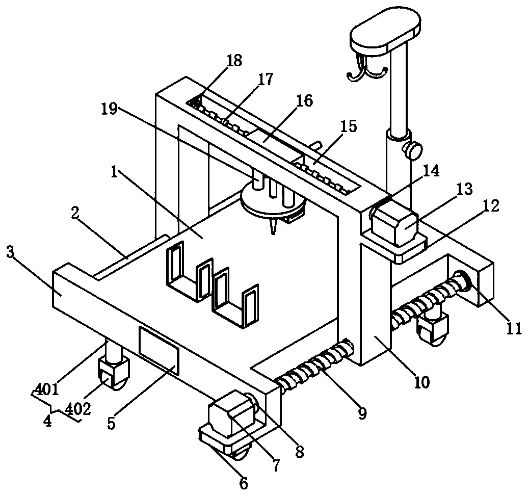
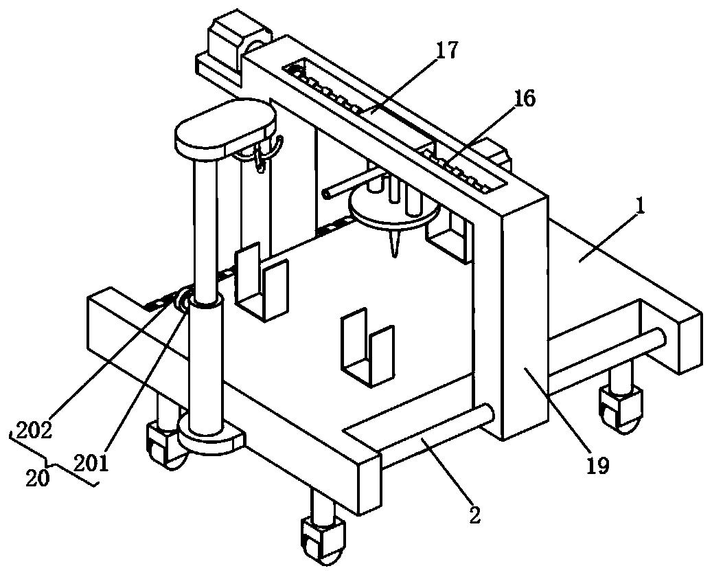
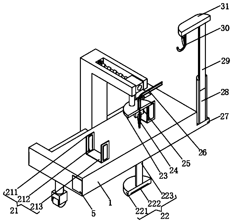
[0028] see Figure 1-3 , the present invention provides a technical solution: a cardiovascular internal medicine effusion drainage device, including a bed body 1, a control switch group 5, a servo motor 1 7 and a servo motor 2 13;

[0029]Bed body 1: the edge of the lower end surface of the bed body 1 is provided with evenly distributed moving structure 4, the moving structure 4 includes a support rod 401, the upper end of the support rod 401 is connected to t...


PUM


Abstract

The invention discloses an effusion drainage device for a cardiovascular medicine department. The device includes a bed, a control switch set, a first servo motor and a second servo motor; a uniformly distributed moving structure is arranged on the edge of the lower end face of the bed, an auxiliary fixing structure is arranged on the middle part of the lower end face of the bed, two outer plates which are opposite in front and back are connected to the left and right end of the bed separately, a guide rod is connected between the two outer plates at the left end, a first lead screw is connected between the two outer plate at the right end, the first lead screw is in threaded connection with the lower side of the right end of a portal frame, the guide rod is in slidable connection with the lower side of the left end of the portal frame, and a guide sliding grove is formed in the middle part of the transverse plate of the portal frame. According to the effusion drainage device for the cardiovascular medicine department, by arranging the corresponding fixing structure, a patient undergoing drainage can be fixed, and additional pain caused by the patient's own movements during drainage is avoided; by arranging a corresponding infusion bottle hanging structure, infusion bottle hanging can be achieved.

Description

technical field [0001] The invention relates to the technical field of medical devices, in particular to a drainage device for effusion in cardiovascular medicine. Background technique [0002] Common effusions in cardiovascular medicine mainly include pericardial effusion, which is common in acute pericarditis, chronic pericarditis, uremia, hypoproteinemia, tumor pericardial metastasis, traumatic pericarditis, acute myocardial infarction and other diseases. The generation of effusion will cause symptoms such as dyspnea, orthopnea, distended jugular veins, and paranormal pulse. In order to ensure the safety of the patient’s life, it is necessary to quickly extract the effusion in the pericardium, and the extraction of pericardial effusion requires drainage. Devices, such as the patent application publication code 201820243402.8, which discloses a cardiovascular medicine effusion drainage device, but there are certain defects in the use of this patent. On the one hand, the fu...

Claims


Application Information

Patent Timeline
Patent Type & Authority Applications(China)
IPC IPC(8): A61G13/00A61G13/10A61G13/12A61M1/00A61M5/14
CPCA61G13/00A61G13/10A61G13/124A61G13/125A61M1/00A61M5/1415
Inventor 徐卫娟王庆锋
Owner 徐卫娟
Why Eureka
Try Eureka