A Complex Impedance Matched Circularly Polarized Filter Antenna
A filter antenna and complex impedance technology, applied in the field of filter antenna, can solve the problems of increased loss of impedance matching network, introduction of filter, complex structure, etc., to achieve the effect of reducing loss and improving integration
- Summary
- Abstract
- Description
- Claims
- Application Information
AI Technical Summary
Problems solved by technology
Method used
Image
Examples
Embodiment
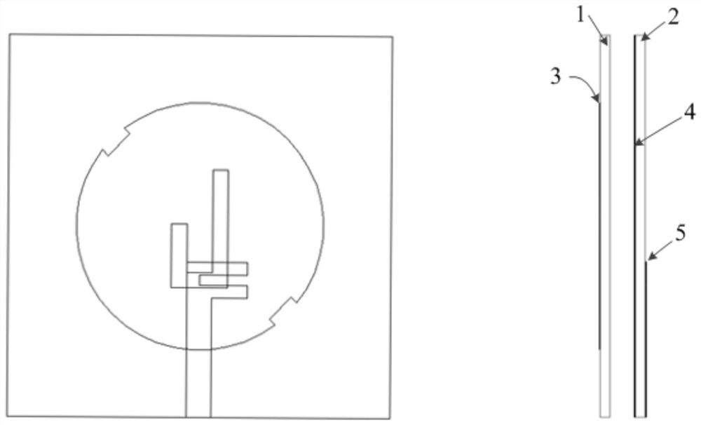
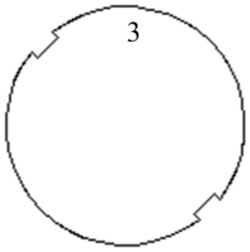
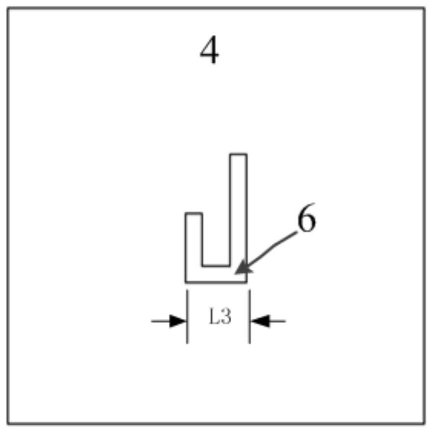
[0031] A simulation study is carried out on an example of a complex impedance matching circularly polarized filter antenna with a working frequency of 5.8GHz. The antenna works at 5.8GHz and is printed on two layers of Rogers 4003C substrates (ε r =3.55, tanδ=0.009), the thickness is 0.813mm. The distance between the two substrates is 2 mm. Radiation elements are etched on the top layer of the upper substrate. It is a circular patch with a notch. Asymmetrical U-shaped slots are etched on the middle floor for circularly polarized radiation. In the feeding structure, a U-shaped microstrip line resonator and a radiation patch are used to form a filtering function.
[0032] A typical input impedance of a specific rectification circuit obtained in the rectification circuit simulation study is 73.5+j106.3Ω as the complex impedance matching target. The input impedance of the filter antenna should be matched to its conjugate for maximum power transfer. A filter antenna with an i...
PUM
 Abstract
Description
Claims
Application Information
 - R&D
- Intellectual Property
- Life Sciences
- Materials
- Tech Scout
- Unparalleled Data Quality
- Higher Quality Content
- 60% Fewer Hallucinations
Browse by: Latest US Patents, China's latest patents, Technical Efficacy Thesaurus, Application Domain, Technology Topic, Popular Technical Reports.
© 2025 PatSnap. All rights reserved.Legal|Privacy policy|Modern Slavery Act Transparency Statement|Sitemap|About US| Contact US: help@patsnap.com


