Broadband Miniaturized Low Profile Dual Polarized Antenna Based on Artificial Magnetic Conductor
A technology of artificial magnetic conductors and dual-polarized antennas, applied in antennas, resonant antennas, electrical short antennas, etc., can solve the problems of high profile, large size, and narrow bandwidth of dual-polarized antennas, and achieve miniaturization and broadband characteristics, effects of antenna size reduction
- Summary
- Abstract
- Description
- Claims
- Application Information
AI Technical Summary
Problems solved by technology
Method used
Image
Examples
specific Embodiment approach 1
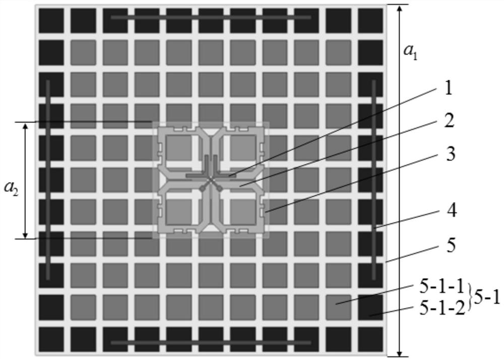
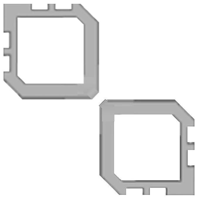
[0027] Specific implementation mode one: combine figure 1 and figure 2 Describe this embodiment in detail, the broadband miniaturized low-profile dual-polarized antenna based on the artificial magnetic conductor described in this embodiment includes a space coupling feeder 1, two dipole antennas 2, and first dielectric plates 3 and 4 Parasitic strip 4, AMC reflective backplane 5 and two 50Ω coaxial cables 6;
[0028] The spatially coupled feeder 1 is printed on the upper surface of the first dielectric plate 3, and the two dipole antennas 2 are vertical and printed on the lower surface of the first dielectric plate 3, and the parasitic strip 4 is formed by the two dipole antennas 2 The intersection points are center-symmetrically distributed around the first dielectric plate 3, and the AMC reflective backplane 5 is located below the first dielectric plate 3;
[0029] The two coaxial lines 6 are in one-to-one correspondence with the two dipole antennas 2, and the tops of the...
specific Embodiment approach 2
[0031] Specific embodiment two: this embodiment is to further illustrate the broadband miniaturized low-profile dual-polarized antenna based on the artificial magnetic conductor described in specific embodiment one. In this embodiment, the AMC reflective backplane 5 includes m periodic Metal unit 5-1, second dielectric plate 5-2, air cavity 5-3 and metal reflection plate 5-4;
[0032] m periodic metal units 5-1 are arranged in an equidistant rectangular array, and printed on the upper surface of the second dielectric plate 5-2, the metal reflector 5-4 is located under the second dielectric plate 5-2, and the metal An air cavity 5-3 exists between the reflection plate 5-4 and the second dielectric plate 5-2, and m is a positive integer greater than or equal to 9.
[0033] Both the first dielectric board 3 and the second dielectric board 5-2 are FR4 dielectric boards (relative dielectric constant is 4.4).
[0034] The adoption of the AMC reflective backplane 5 of this embodimen...
specific Embodiment approach 3
[0035] Specific embodiment three: this embodiment is a further description of the broadband miniaturized low-profile dual-polarized antenna based on the artificial magnetic conductor described in the second specific embodiment. In this embodiment, the m periodic metal units 5-1 are a metal patch unit 5-1-1 and b mushroom-shaped unit 5-1-2, a metal patch unit 5-1-1 is arranged in an equidistant rectangular array, and b mushroom-shaped unit 5-1-2 1-2 are located at the periphery of the array;
[0036] Each mushroom-shaped unit 5-1-2 includes a metal patch and a metal column. The top of the metal column is electrically connected to the metal patch through the metal via hole on the second dielectric board 5-2, and the bottom end of the metal column is connected to the metal column. The reflector 5-4 is connected.
[0037] The periodic metal unit 5-1 adopts two kinds of units, the metal patch unit 5-1-1 and the mushroom-shaped unit 5-1-2, which effectively improves the cross-polar...
PUM
 Abstract
Description
Claims
Application Information
 - R&D
- Intellectual Property
- Life Sciences
- Materials
- Tech Scout
- Unparalleled Data Quality
- Higher Quality Content
- 60% Fewer Hallucinations
Browse by: Latest US Patents, China's latest patents, Technical Efficacy Thesaurus, Application Domain, Technology Topic, Popular Technical Reports.
© 2025 PatSnap. All rights reserved.Legal|Privacy policy|Modern Slavery Act Transparency Statement|Sitemap|About US| Contact US: help@patsnap.com


