Optical cable wiring structure based on POTDR system for measuring disturbance
A wiring structure and optical cable technology, applied in the field of polarized light time domain reflection detection, can solve the problem of no optical cable birefringence sensitivity optical cable wiring method, etc., and achieve the effects of improving sensitivity, large laying area, and improving accuracy
- Summary
- Abstract
- Description
- Claims
- Application Information
AI Technical Summary
Problems solved by technology
Method used
Image

Examples
Embodiment 1
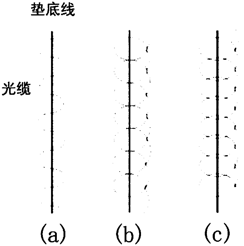
[0044] figure 1 (a) shows the S-shaped wiring structure. Such as figure 1As shown in (a), the optical cable is arranged in an "S" shape on a bottom line. According to the analysis of the working principle, if the phase difference caused by the bending birefringence δ≥0.02π, the downward bending radius R≤68mm caused by stepping is required. However, due to the limitation of the height of the base, it can be obtained that the distance between the contact end of the optical cable and the ground and the base is l, and the length of the optical cable affected by the bending is about The actual phase difference change is less than 0.02π. In order to achieve the required phase difference, it is necessary to further reduce the radius of the downward bend. According to the calculation, the required downward bending radius is R=30mm, and the length of the affected optical cable at this time is 8.71πmm. At this time, the force required to make the optical cable bend like this is ...
Embodiment 2
[0047] figure 1 (b) shows the ring wiring structure. Such as figure 1 As shown in (b), the optical cable is laid on the base line in a ring shape. In this wiring structure, the induced birefringence is still mainly caused by bending. The layout parameters are approximately equal to those in the S"-shaped wiring scheme, but the difference is that due to the circular layout, under the same external event, the length of the affected optical cable becomes twice that of Embodiment 1. Due to more The optical cable disperses the force of stepping on it, so the pressure per unit length of the optical cable will be less than that of the "S" shape wiring scheme. But because the length of the affected optical cable has doubled, the overall sensitivity is better than that of embodiment one, but for the same monitoring area, the required cable length will double.
[0048] In this embodiment, we bend and fix the optical cable on the bottom line according to the loop wiring method, and t...
Embodiment 3
[0050] figure 1 (c) shows the overlapping ring wiring structure. Such as figure 1 As shown in (c), in the overlapping ring wiring structure, the overlapping ring layout is similar to the ring layout, but on the basis of it, the following circular arc line is placed on the previous circular arc line, so there are more bending points, The higher degree of bending can significantly improve the sensitivity of the system on the second wiring scheme.
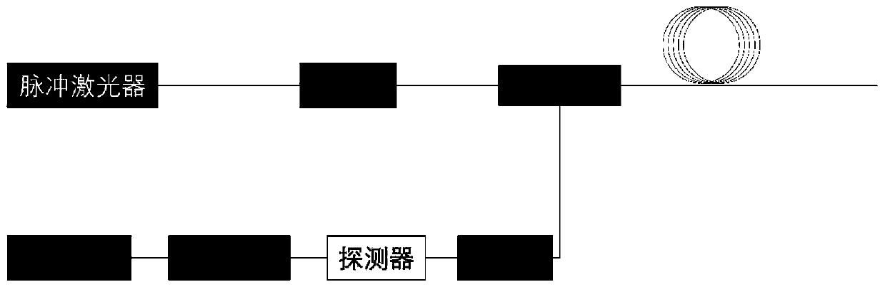
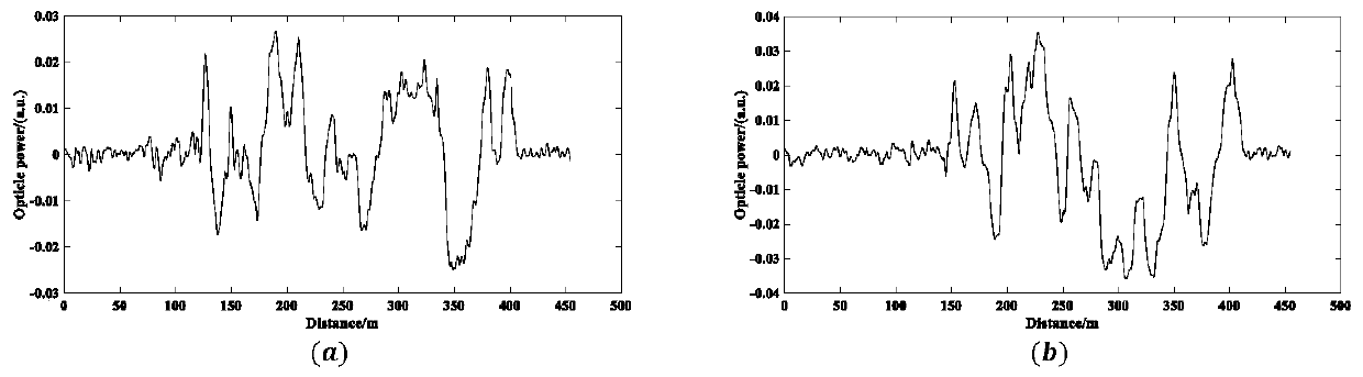
[0051] In this embodiment, we bend and fix the optical cable on the bottom line according to the loop wiring method, and then place the optical cable on the figure 2 Between the coupler and the polarizer, the optical fiber signal is collected in different places of the optical cable by taking the walking of a normal person as an example. Then the collected signal is processed with MATLAB software, in which Figure 5 is the differential curve result of the polarization signal obtained by applying pressure at two different position...
PUM
| Property | Measurement | Unit |
|---|---|---|
| Diameter | aaaaa | aaaaa |
| Bending radius | aaaaa | aaaaa |
Abstract
Description
Claims
Application Information
 - R&D
- Intellectual Property
- Life Sciences
- Materials
- Tech Scout
- Unparalleled Data Quality
- Higher Quality Content
- 60% Fewer Hallucinations
Browse by: Latest US Patents, China's latest patents, Technical Efficacy Thesaurus, Application Domain, Technology Topic, Popular Technical Reports.
© 2025 PatSnap. All rights reserved.Legal|Privacy policy|Modern Slavery Act Transparency Statement|Sitemap|About US| Contact US: help@patsnap.com