Fireproof door

A technology of fire doors and fire bars, which is applied in the field of fire doors, can solve problems such as dense smoke, large safety hazards, and unfavorable escape, and achieve the effect of lowering the temperature

Active Publication Date: 2019-09-13
湖南消安建材有限公司
View PDF6 Cites 5 Cited by
  • Summary
  • Abstract
  • Description
  • Claims
  • Application Information

AI Technical Summary

Problems solved by technology

However, these fire doors have the same problem in the event of a fire, that is, when the fire door is opened, the safe area and the fire area are connected, so that a large amount of smoke will be poured into the safe area, resulting in The smog is not conducive to escape, and it will also bring safety hazards to those who escaped smoothly
Furthermore, burnt debris will randomly fall from the ceiling of the fire area, which poses a certain danger to the escapees who pass through the fire door, and the location of the fire door is relatively inconspicuous, and it is not easy to be noticed
[0003] Finally, because the survivors may carry flames, these flames may not be discovered by the survivors. If they are not extinguished at this time, they are likely to burn all over the body. Even if the escape is successful, there will be a large area of ​​skin burns, which is a great safety hazard.
At the same time, because the fire door is a single-layer or multi-layer door panel, it will still be damaged after the transitional contact with the flame, which will lead to the entire safety area, and a large amount of smoke will pour in to bring a very large safety hazard to the escape.

Method used


Image

  • Fireproof door
  • Fireproof door
  • Fireproof door

Examples


Embodiment Construction

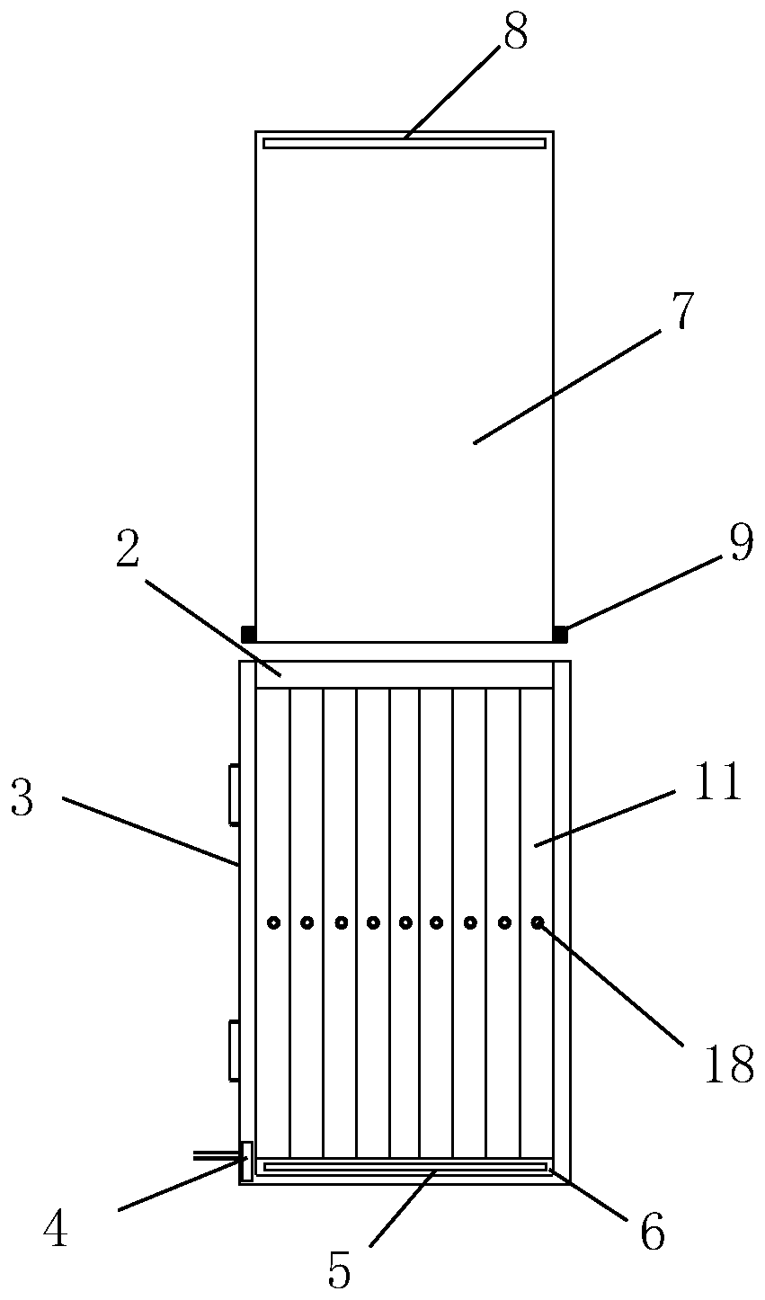
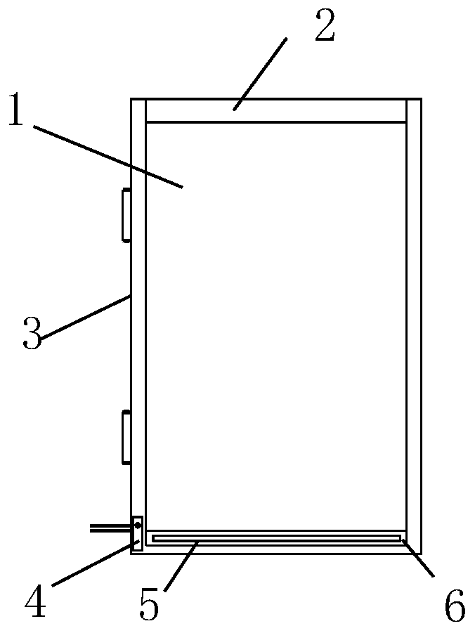
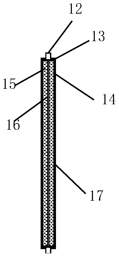
[0022] Such as figure 1 with figure 2 As shown, a fire door includes a door frame 3, a hollow cavity 1 through which the door frame 3 has a middle, and the upper and lower sides of the hollow cavity 1 are respectively provided with more than one group of symmetrical first shaft holes (not shown), the hollow There are more than one flexible fireproof rods 11 arranged side by side in the cavity 1. The fireproof rods 11 and the fireproof rods 11 are in sealing contact with each other and the entire hollow cavity 1 is sealed by more than one fireproof rods 11. The upper and lower sides of the fireproof rods 11 are respectively vertical. A first rotating shaft 12 is provided, and the first rotating shafts 12 are respectively rotated and installed in the first rotating shaft holes (not shown) above and below the hollow cavity, and an escape gap cavity is formed between two adjacent fireproof rods 11;

[0023] The front and back of the door frame 3 are respectively provided with a ...


PUM


Abstract

The invention discloses a fireproof door. The fireproof door comprises a door frame, wherein a hollow through cavity is formed in the middle of the door frame, and a more than one group of symmetricalfirst shaft hole are separately formed in the upper surface and the lower surface of the hollow cavity, and more than one flexible fireproof rod is arranged in the hollow cavity side by side; the fireproof rods are in sealing contact with each other, and the whole hollow cavity is sealed by the more than one fireproof rod; first rotating shafts are vertically disposed on the upper side and the lower side of the fireproof rods separately, and the first rotating shafts are rotatably mounted into the first rotating shaft holes formed in the upper surface and the lower surface of the hollow cavity; and an escape gap cavity is formed between the every two adjacent fireproof rods. The novel new fireproof door is adopted, the smoke can be effectively blocked from entering an escape space duringescape, and the heat on an escaper can be effectively reduced, the fireproof time of the fireproof door is further prolonged, and the function of safety protection is achieved.

Description

technical field [0001] The invention relates to a door, in particular to a fireproof door. Background technique [0002] In buildings, there are usually many fire escape doors between the safety area and the living area. These doors are usually closed and rarely opened, so these fire doors cannot be blocked. However, these fire doors have the same problem in the event of a fire, that is, when the fire door is opened, the safe area and the fire area are connected, so that a large amount of smoke will be poured into the safe area, resulting in The smog fills the air, which is not conducive to escape, and will also bring safety hazards to people who escaped smoothly. In addition, burnt debris will randomly fall from the ceiling of the fire area, which is dangerous to the escapees who pass through the fire door. Moreover, the location of the fire door is relatively inconspicuous, and it is not easy to be noticed. [0003] Finally, because the survivors may carry flames, these ...

Claims


Application Information

Patent Timeline
Patent Type & Authority Applications(China)
IPC IPC(8): E06B5/16E06B7/28E06B3/70
CPCE06B3/70E06B5/16E06B7/28E06B2003/7057
Inventor 周梅英
Owner 湖南消安建材有限公司
Why Eureka
Try Eureka