Eureka AIR delivers breakthrough ideas for toughest innovation challenges, trusted by R&D personnel around the world.

Textile intelligent carding machine

A carding machine, an intelligent technology, applied in textile and papermaking, mechanical cleaning, de-floating yarn, etc., can solve the difficulty of increasing the hairball, scraping out the miscellaneous thread, reducing the fluffy feeling of fluff, and the damage of the flannel surface caused by the force of the rake, etc. It can reduce the damage, improve the fluffy feeling, and reduce the area of ​​pressing down.

Active Publication Date: 2019-09-13
扬州金晟华线业有限公司
View PDF6 Cites 8 Cited by
  • Summary
  • Abstract
  • Description
  • Claims
  • Application Information

AI Technical Summary

Problems solved by technology

[0006] The present invention can solve the problem that during the carding process, personnel usually use a rake to comb the fluff surface. Because the contact area between the tooth end of the rake and the flannelette is relatively large, it is easy to crush the fluff during the carding process so that it is difficult to straighten out the direction of the fluff. The fluffy feeling of the fluff is reduced, and the rake may cause damage to the flannel surface due to the uneven strength of the personnel during operation. Due to the large area of ​​the tooth end of the rake, it is difficult to scrape out the hair balls and miscellaneous threads in the deep layer of the fluff surface. Sometimes it is easy for the teeth of the rake to push the hair balls and miscellaneous threads downward, which increases the difficulty of scraping the hair balls and miscellaneous threads, and the scraped hair balls and miscellaneous threads often fall into the surrounding fluff surface, etc. problem

Method used


Image

  • Textile intelligent carding machine
  • Textile intelligent carding machine
  • Textile intelligent carding machine

Examples


Embodiment Construction

[0033] Embodiments of the present invention will be described below with reference to the drawings. In the process, in order to ensure the clarity and convenience of illustration, we may exaggerate the width of the lines or the size of the constituent elements in the diagram.

[0034] In addition, the following terms are defined based on the functions in the present invention, and may be different according to the user's or operator's intention or practice. Therefore, these terms are defined based on the entire content of this specification.

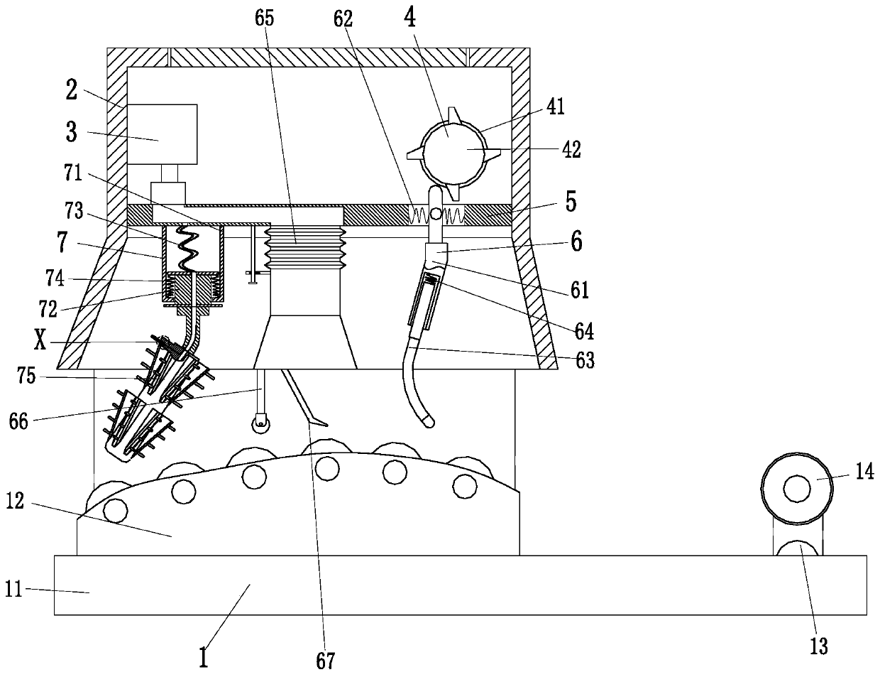
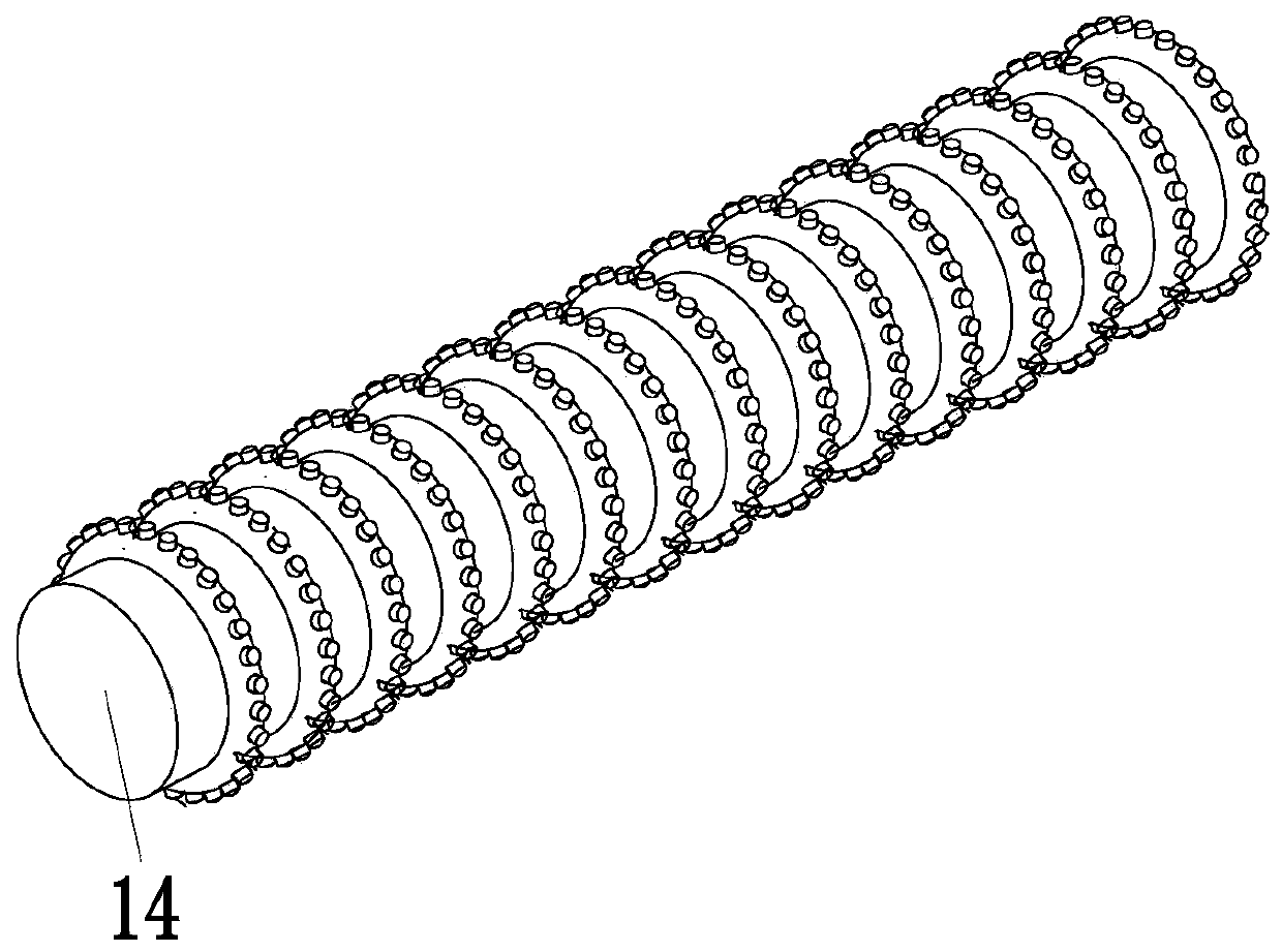
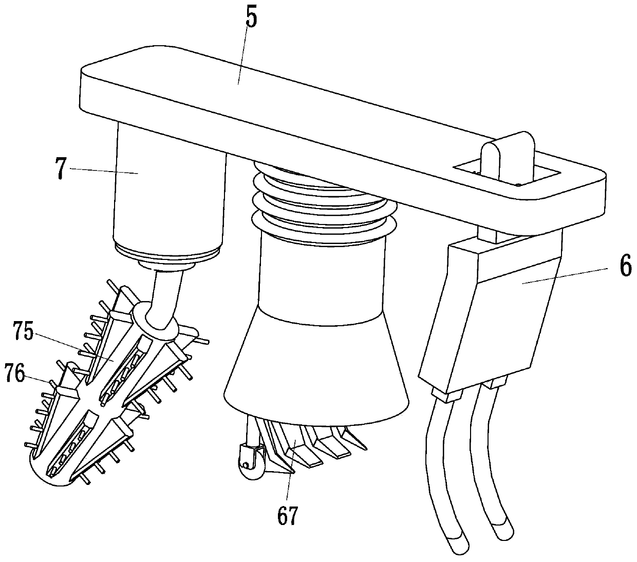
[0035] like Figure 1 to Figure 5 As shown, a textile intelligent carding machine includes a conveying bed 1, a dustproof frame 2, a vacuum cleaner 3, a driving device 4, a fixed plate 5, a dust suction device 6 and a carding device 7, and the left end of the conveying bed 1 is A dust-proof frame 2 is installed, a vacuum cleaner 3 is installed on the left end of the dust-proof frame 2, a driving device 4 is installed on the right end o...


PUM


Abstract

The invention relates to a textile intelligent carding machine. The textile intelligent carding machine comprises a conveying bed body, a dust-proof box, a dust collector, a driving device, fixed plates, dust suction devices and carding devices, wherein the dust-proof box is mounted at the left end of the conveying bed body; the dust collector is mounted at the left end of the interior of the dust-proof box; the driving device is mounted at the right end of the interior of the dust-proof box; the fixed plates are uniformly mounted on the lower side of the interior of the dust-proof box; a carding device is arranged at the left end of each fixed plate; the dust suction device is arranged at the right end of each fixed plate. The textile intelligent carding machine can solve the problems that personnel usually card fuzzing surfaces by a rake, as a contact area between tooth ends of the rake and flannelette is large, fuzz presses down easily during carding, and the direction of the fuzz is difficult to straighten; as the area of the tooth ends of the rack is large, fuzzy balls and miscellaneous lines in deep layers of the fuzzing surfaces are difficult to scrape, and the situation that the tooth ends of the rack downward pushes the fuzzy balls and miscellaneous lines during scraping easily occurs.

Description

technical field [0001] The invention relates to the field of textile carding, in particular to an intelligent textile carding machine. Background technique [0002] Carding is a very important step in the textile process. Different textile fabrics need to be carded in different ways, and a suitable carding machine should be selected for carding. Among them, flannelette is a kind of cotton with a rich and fluffy surface after brushing. Fabric has a lot of fluff attached to the fluff, and the fluff surface needs to be combed to remove impurities. Personnel usually use a rake-type manual combing method to comb the fluff surface. However, the following problems often exist during the carding process: [0003] 1. Personnel usually use a rake to comb the fluff surface. Because the tooth end of the rake has a large contact area with the flannelette, it is easy to crush the fluff during the carding process, making it difficult to straighten out the direction of the fluff, and the fl...

Claims


Application Information

Patent Timeline
IPC IPC(8): D06C13/06D06G1/00
CPCD06C13/06D06G1/00
Inventor 倪新贺张皖龙张伟健
Owner 扬州金晟华线业有限公司
Why Eureka
Eureka Blog
Learn More