Gear-shifting method for electric drive system

A technology of an electric drive system and a shifting method, which is applied to electric power devices, motor vehicles, power devices, etc., and can solve problems such as motors not being able to decelerate vehicles

Pending Publication Date: 2019-09-13
ZF FRIEDRICHSHAFEN AG
View PDF7 Cites 0 Cited by
  • Summary
  • Abstract
  • Description
  • Claims
  • Application Information

AI Technical Summary

Problems solved by technology

[0008] The disadvantage of the above-mentioned known electric drive system is that the electric motor cannot play the role of decelerating the vehicle during the shifting period.

Method used


Image

  • Gear-shifting method for electric drive system
  • Gear-shifting method for electric drive system

Examples


Embodiment Construction

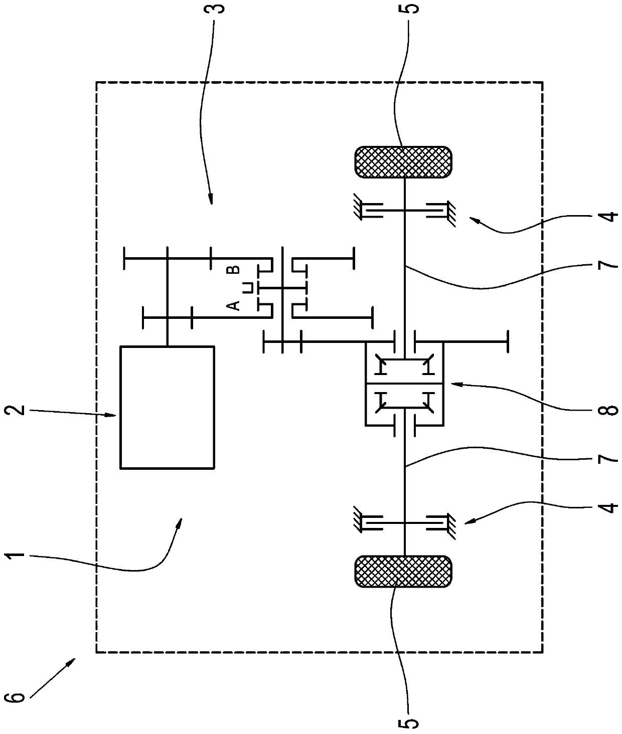
[0029] figure 1 A portion of an electric vehicle 6 is shown. The electric vehicle 6 has an electric drive system 1 with an electric machine 2 , a gearbox 3 and a brake 4 for braking wheels 5 . The electric motor 2 is drive-connected to the gearbox 3 , wherein the gearbox 3 is downstream of the electric motor 2 in terms of drive. exist figure 1 In the embodiment shown, the brake 4 is arranged on a shaft 7 drivable by the electric motor 2 . The shifting method according to the invention also functions when the brake 4 is arranged on another shaft which cannot be driven via the brake 4 .

[0030] The gearbox 3 includes a differential gearbox 8 via which the electric machine 2 can be drive-connected to the wheels 5 . Wheel 5 is drive-connected to shaft 7 . In this case, a respective brake 4 is assigned to each wheel 5 .

[0031]Transmission 3 is a 2-speed transmission with two spur gear stages. In order to realize the two gears, the gearbox 3 has a first shifting element A ...


PUM


Abstract

The invention relates to a gear-shifting method for an electric drive system, the electric drive system (1) including an electric machine (2), a multi-stage transmission (3) drivingly connected downstream from the electric machine (2) and having interruption of tractive force, and at least one brake (4) for braking a vehicle wheel (5), the method including transferring the brake (4) out of an inoperative condition into a readiness condition during a gear-shifting operation of the transmission (3). Furthermore, the present invention relates to an electric drive system for implementing the gear-shifting method and an electric vehicle having such an electric drive system.

Description

technical field [0001] The invention relates to a gearshift method for an electric drive system comprising an electric machine, a multi-gear transmission with traction interruption and at least one gear for braking the wheels. brakes. [0002] Furthermore, the invention also relates to an electric drive system utilizing this shifting method. Furthermore, the invention relates to an electric vehicle with an electric drive system. Background technique [0003] Many electric vehicles are known from the prior art which comprise an electric drive system with a fixed transmission ratio. This means that only one single gear can be realized with this electric drive system. Such electric vehicles have a simple construction and comfortable driving performance. The downside, however, is that when choosing a gear ratio, a compromise must be found between tractive effort at start-up and possible final speed. Furthermore, the rotational speed level of the electric motors of such elec...

Claims


Application Information

Patent Timeline
Patent Type & Authority Applications(China)
IPC IPC(8): B60W30/19B60T7/12B60K1/00
CPCB60W30/19B60T7/12B60K1/00B60W10/11B60W10/184B60Y2200/91B60W2710/18B60W2520/105B60W2710/1005B60W2510/101B60W2554/00
Inventor 约翰尼斯·卡尔滕巴赫马蒂亚斯·霍恩
Owner ZF FRIEDRICHSHAFEN AG
Why Eureka
Try Eureka