A wire cutting and anti-stripping device

A wire and anti-scattering technology, which is applied in the field of electric power construction auxiliary equipment, can solve problems such as unfavorable wire cutting, and achieve the effects of improving efficiency and safety, improving efficiency, and increasing contact area

Active Publication Date: 2020-06-02
QINGHAI POWER TRANSMISSION & TRANSFORMATION ENG +2
View PDF1 Cites 0 Cited by
  • Summary
  • Abstract
  • Description
  • Claims
  • Application Information

AI Technical Summary

Problems solved by technology

It utilizes gears meshing with the racks on the outside of the pressing plate to realize fast binding of the wires through the rotation of the gears. However, during use, it was found that due to the different specifications of the wires, when the supporting plate and the pressing plate crimp the wires, the supporting plate and the pressing plate are different. A space similar to an ellipse is formed between the pressure plates, and there are gaps at both ends of the long axis of the ellipse, so that there are different degrees of loose strands on both sides of the wire, and the smaller the diameter of the wire, the more obvious the loose strands are, which is not conducive to the cutting of the wire

Method used


Image

  • A wire cutting and anti-stripping device
  • A wire cutting and anti-stripping device
  • A wire cutting and anti-stripping device

Examples


Embodiment 1

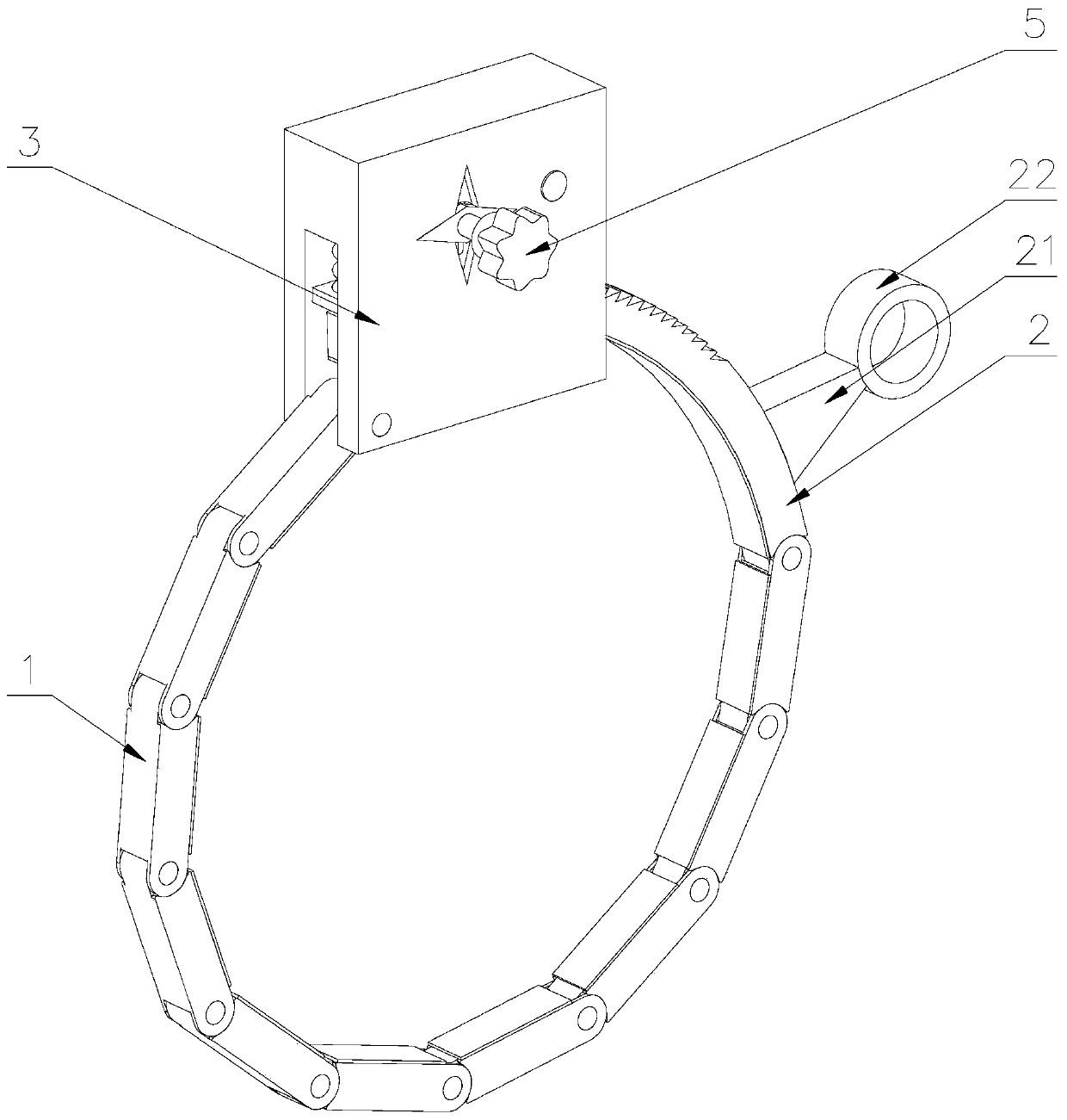
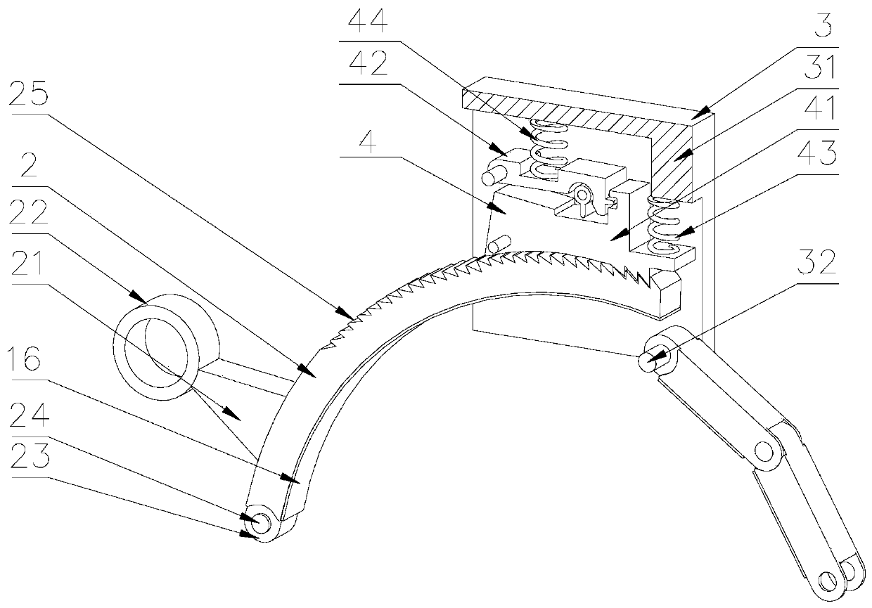
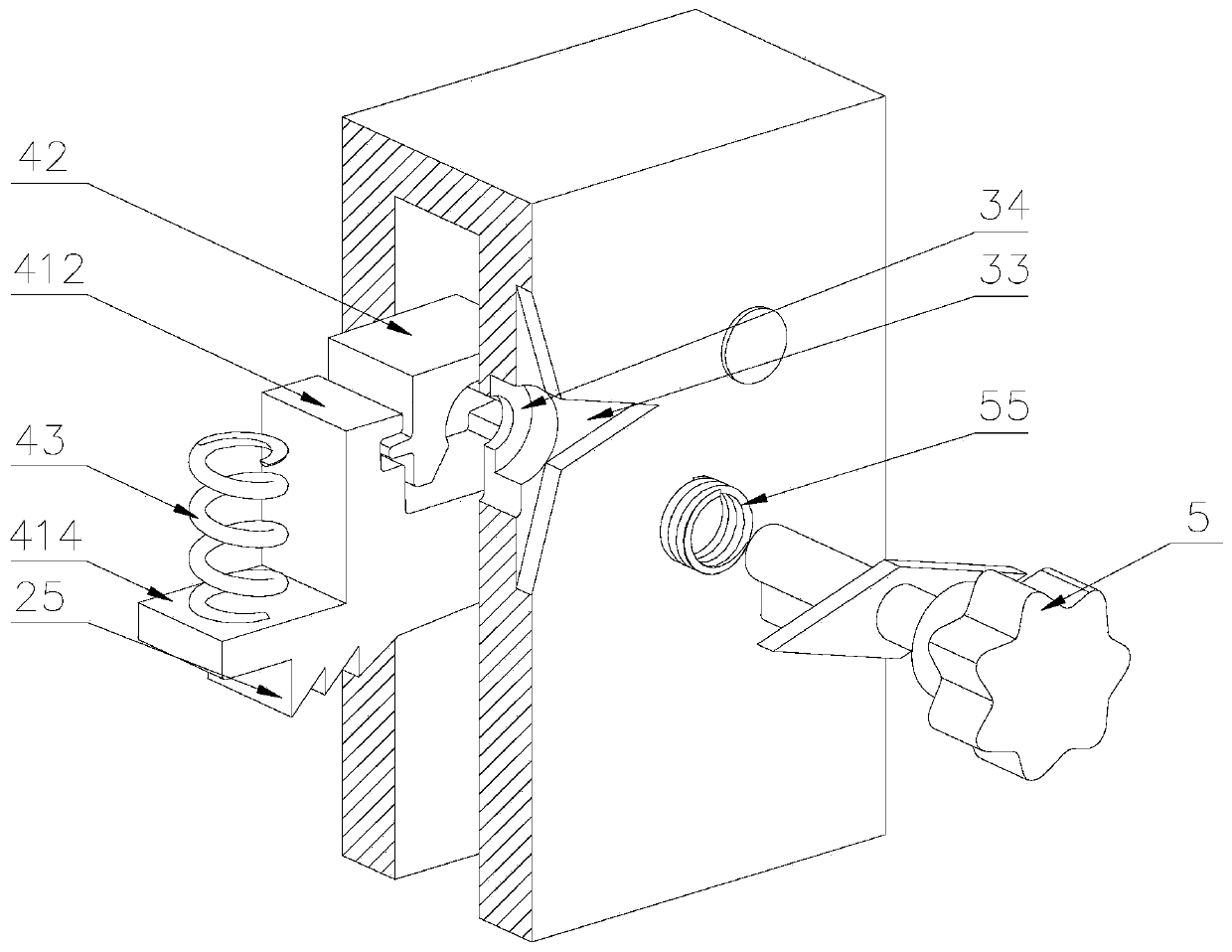
[0047] A wire cutting anti-strand device, including a first connecting arm 1, a second connecting arm 2, a first shield 3, a locking mechanism 4, and an unlocking device 5, the first connecting arm 1 is provided with several groups, the One end of the first connecting arm 1 is provided with a first groove 12, and both sides of the first groove 12 are provided with a clamping plate 11, and a connecting hole 13 is provided on the clamping plate 11; One end is provided with a first hinged joint 14, and first pin shafts 15 are provided on both sides of the first hinged joint 14, and the first pin shafts 15 are movably connected with the connecting holes 13 on the clamping plate 11; multiple sets of first connecting arms 1. The first pin shaft 15 and the connecting hole 13 are sequentially connected to form a flexible connecting arm. When crimping the wire, a circular gap is formed between the first connecting arm 1 and the second connecting arm 2, which increases the gap between th...

Embodiment 2

[0055] The difference from Embodiment 1 is that the locking mechanism 4 includes a rotating shaft 46 and a rocker 48, a second shield 6 is provided on one side of the first shield 3, and one end of the rotating shaft 46 is movably installed on the second On one side of the shield 3, the other end of the rotating shaft 46 is movably installed on one side of the second shield 6; the rotating shaft 46 is fixedly equipped with a second ratchet 47, and the second ratchet 47 is located on the first shield. Inside the cover 3, and the ratchet 25 of the second ratchet 47 is matched with the ratchet 25 of the second connecting arm 2; a first ratchet 45 is provided on one side of the second ratchet 47, and the first ratchet 45 is located on the second Inside the shield 6; the rocking bar 48 is positioned at one side of the second ratchet 47, and the lower end of the rocking bar 48 is fixedly installed on the rotating shaft 46, and one side of the upper part of the rocking bar 48 is provi...

Embodiment 3

[0059] The difference from Embodiment 1 and Embodiment 2 is that when this wire cutting and anti-strand device is used together to cut the middle section of the wire, in order to ensure that the wire is in a tight state, a connection is provided between the two sets of wire cutting and anti-strand devices. device 7, the connection device 7 includes a stud 71, a through hole is provided on the first connecting rod 22, the stud 71 is located inside the through hole, and a first nut is provided on one side of the first connecting rod 22 72. The other side of the first connecting rod 22 is provided with a second nut 73. According to the needs of the construction site, adjust the distance between the two groups of wire cutting and anti-stripping devices, and make the wires in a tight state, and then pass through the first Nut 72 and the second nut 73 fix the positions of the two groups of wire cutting anti-stripping devices, ensuring that the wires are in a tight state, which not on...


PUM


Abstract

The invention discloses a wire cutting anti-strand device. There are several groups of first connecting arms, and multiple groups of first connecting arms are sequentially connected through first pin shafts and connecting holes to form flexible connecting arms; the first connecting arm at the head end passes through The third pin shaft is movably connected with the first shield, the first connecting arm at the end is provided with a second connecting arm, and the upper side of the second connecting arm is provided with several ratchets; the inside of the first shield is provided with a lock The locking mechanism cooperates with the ratchet teeth on the second connecting arm; one side of the locking mechanism is provided with an unlocking device; the wire cutting and anti-stripping device can be used alone or in combination. In the present invention, a plurality of sets of first connecting arms are provided, and the multiple groups of first connecting arms are sequentially connected through first pin shafts to form flexible connecting arms. The gap increases the contact area between the connecting arm and the wire, and avoids the phenomenon of loose strands of the wire.

Description

technical field [0001] The invention belongs to the technical field of electric power construction auxiliary equipment, and in particular relates to a device for preventing strands from cutting wires. Background technique [0002] The production method of the aluminum stranded wire is to use a cutting saw blade to cut the wire. If the wire is cut directly, it will cause the aluminum stranded wire to loose strands. In order to strengthen quality management and improve the construction technology level of power infrastructure projects, during the installation of soft busbars in substations, before the wires are crimped, the front wires of the aluminum tube openings need to be fastened with iron wire or aluminum wire to prevent loose strands during the wire crimping process. ; In order to avoid this phenomenon, but the iron wire or aluminum wire is easily deformed by the impact force generated when the aluminum stranded wire expands, resulting in the phenomenon of loose strands...

Claims


Application Information

Patent Timeline
Patent Type & Authority Patents(China)
IPC IPC(8): B21F11/00
CPCB21F11/00
Inventor 张灵利吴建平吴兴波程志国杨涛郑国彪甘世龙刘得军李敏杰
Owner QINGHAI POWER TRANSMISSION & TRANSFORMATION ENG
Why Eureka
Try Eureka