
Demand response terminal and system and control method of system

A technology of demand response and control method, applied in the direction of information technology support system, power network operating system integration, climate sustainability, etc. Management and other issues to achieve the effect of functional diversification

Inactive Publication Date: 2019-09-10
JIANGSU ELECTRIC POWER CO +1
View PDF0 Cites 0 Cited by
  • Summary
  • Abstract
  • Description
  • Claims
  • Application Information

AI Technical Summary

Problems solved by technology

At present, the equipment that is widely used in the management of large users' electricity consumption is the special transformer collection terminal, but it has the following disadvantages: the special transformer collection terminal is only used to collect the electricity consumption information of large users, and can only provide power consumption information to power supply companies. It cannot realize the management of power consumption by power supply enterprises, that is, it can only provide power consumption data to power supply enterprises in one direction, and cannot realize the interaction between power supply enterprises and power consumption enterprises, and the function is relatively single

Method used


Image

  • Demand response terminal and system and control method of system
  • Demand response terminal and system and control method of system
  • Demand response terminal and system and control method of system

Examples


Embodiment 1

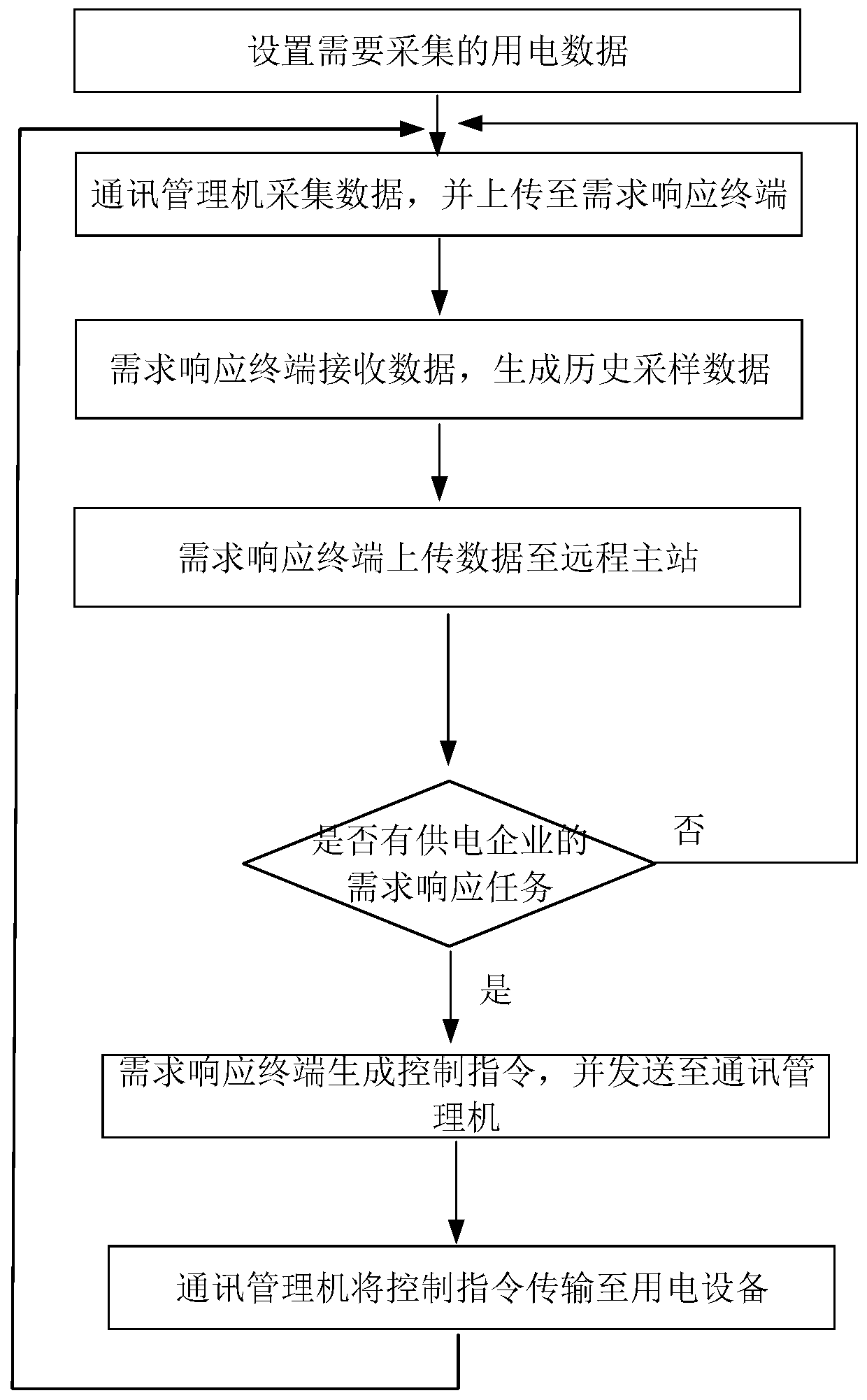
[0074] In this embodiment, the demand response system is a central air-conditioning demand response system for an office building, which includes a remote master station 40 of a power supply company, a demand response terminal 10, a communication management machine 20, and five central air conditioners. Electrical equipment 30. The communication management machine 20 is connected to the centralized controller of the central air conditioner, and collects electricity consumption data through the centralized controller. The communication management machine 20 is connected to the demand response terminal 10 by communication, so that the two The demand response terminal 10 and the remote master station 40 are connected by communication so that the two can also transmit data to each other. The demand response terminal 10 enables the remote master station 40 and the remote master station 40 to communicate with each other. Two-way communication is realized between the above electric d...

Embodiment 2

[0083] In this embodiment, the demand response system is a commercial center comprehensive power supply demand response system, which includes a remote master station 40 of a power supply company, a demand response terminal 10, a communication management machine 20, two central air conditioners, a cold storage, The electrical equipment including a game center, the communication management machine 20 is connected with the centralized controller of the central air conditioner, cold storage and game center at the same time, and collects power consumption data through the centralized controller, and the communication management machine 20 is connected with the centralized controller of the game center The demand response terminal 10 is connected by communication, so that the two can transmit data to each other, and the demand response terminal 10 is connected by communication with the remote master station 40, so that the two can also transmit data to each other, The demand respons...


PUM


Abstract

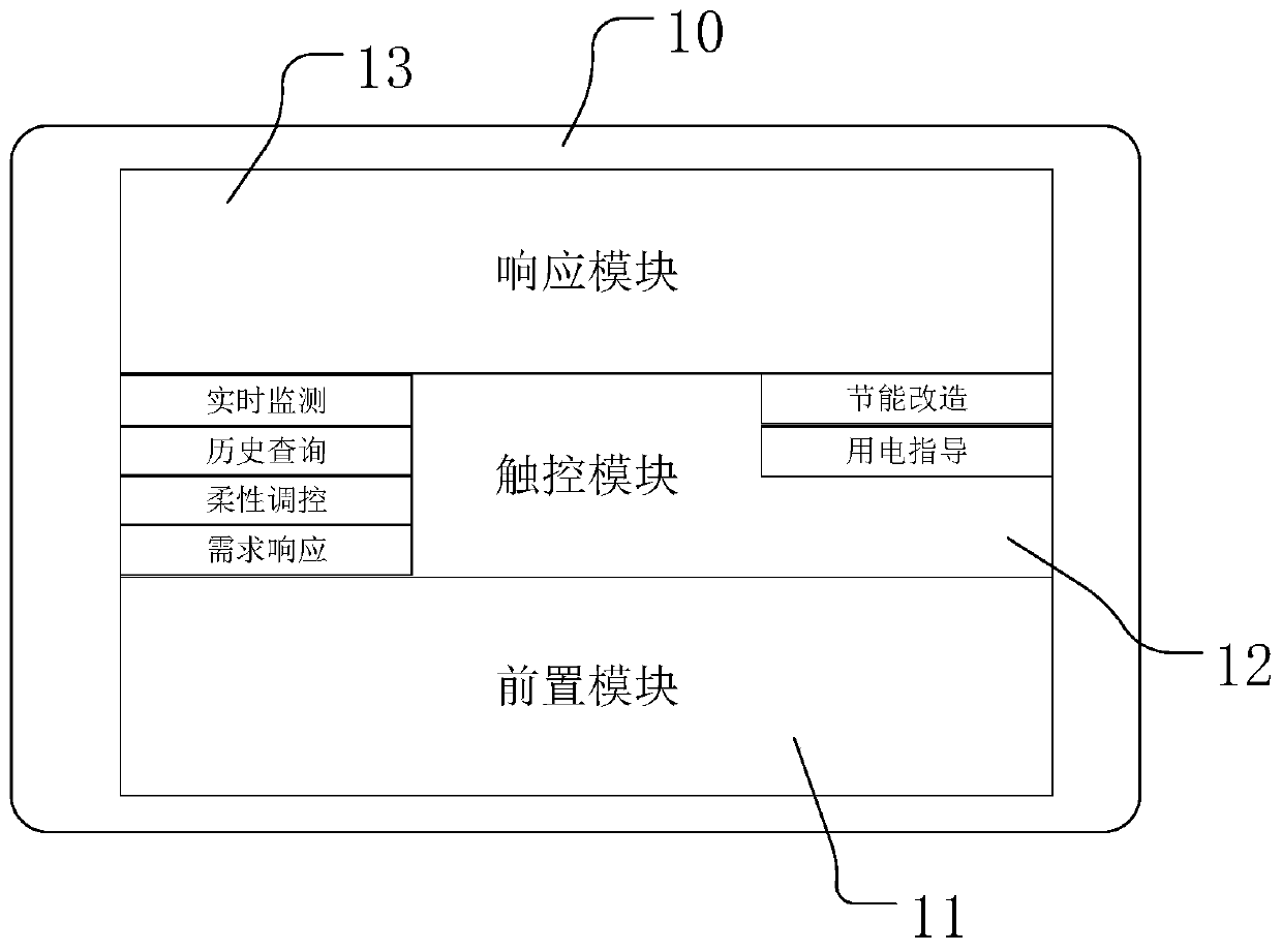
The invention discloses a demand response terminal and system and a control method of the system. The demand response terminal includes a pre-module, a touch control module and a response module. Thepre-module is in communication connection with a communication manager outside the demand response terminal, and is used for receiving and processing electricity consumption data. The touch control module is communication connection with the pre-module, and is used for displaying the electricity consumption data and inputting field operation instructions. The response module is in communication connection with a remote master station, and is used for uploading the electricity consumption data and receiving demand response tasks from the remote master station. The pre-module generates control instructions according to the demand response tasks and transmits the control instructions to electric equipment. Bidirectional data transmission between the remote main station of the power supply enterprise and the electric equipment can be realized, so that the power supply enterprise not only can know the electricity consumption situation of the electric equipment at any time, but also can control the electric equipment. The power supply enterprise and users can interact with each other, and the functions of the demand response terminal can be more diversified.

Description

technical field [0001] The invention relates to the related technical field of power grid demand and load control, in particular to a demand response terminal, a system and a control method for the system. Background technique [0002] With the increasing power consumption of large users, energy consumption is becoming more and more serious. This not only brings huge pressure on environmental protection and energy, but also brings considerable economic pressure to electricity companies. The cost of electricity consumption has become a constraint. An important factor in the profitability of the operator. [0003] In order for power supply companies to understand the power consumption of power-consuming companies, companies with large power consumption generally use power management equipment to understand and control power consumption. At present, the equipment that is widely used in the management of large users' electricity consumption is the special transformer collection...

Claims


Application Information

Patent Timeline
Patent Type & Authority Applications(China)
IPC IPC(8): H02J13/00
CPCH02J13/0062H02J13/00H02J13/00001Y04S20/242Y02B70/30
Inventor 刘凌燕阮涛高晓雷刘晓婕邵林毛科伟汪鹏程宋杰陈良亮朱庆
Owner JIANGSU ELECTRIC POWER CO
Learn More