Welding device of CO2 ceramic lining

A technology for ceramic gaskets and welding devices, applied in welding equipment, arc welding equipment, manufacturing tools, etc., can solve the problems of low efficiency, constant height adjustment, easy displacement, etc., and achieves scientific and reasonable structure, safe and convenient use. , height adjustable effect

Inactive Publication Date: 2019-09-10
鹤壁天宏钢结构有限公司
View PDF16 Cites 1 Cited by
  • Summary
  • Abstract
  • Description
  • Claims
  • Application Information

AI Technical Summary

Problems solved by technology

[0003] In the past, all steel plate splicing welds were double-sided welding (that is, welding on both sides of the front and back), and the back side had to be cleaned to obtain the effect of the first-class weld of ultrasonic flaw detection, which is not only low in efficiency, but also high in cost
The single-sided welding and double-sided forming process of ceramic liner CO2 gas shielded welding is an efficient welding method, but the ceramic liner on the bottom of the weld is the main measure to ensure the quality of the bottoming welding. The existing ceramic liner is used to achieve welding When the ceramic liner is often placed directly under the workpiece to be welded, problems such as displacement are prone to occur during the welding process, resulting in unsatisfactory results after welding, and the height of the existing ceramic liner remains unchanged. It cannot be placed according to the actual height of the required welding fixture. Therefore, in order to solve this series of problems, we propose a CO2 ceramic pad welding device to solve the problem

Method used


Image

  • Welding device of CO2 ceramic lining
  • Welding device of CO2 ceramic lining
  • Welding device of CO2 ceramic lining

Examples


Embodiment Construction

[0016] The following will clearly and completely describe the technical solutions in the embodiments of the present invention with reference to the accompanying drawings in the embodiments of the present invention. Obviously, the described embodiments are only some, not all, embodiments of the present invention. Based on the embodiments of the present invention, all other embodiments obtained by persons of ordinary skill in the art without making creative efforts belong to the protection scope of the present invention.

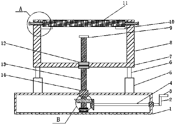
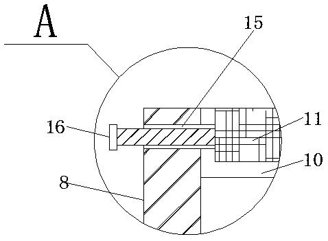
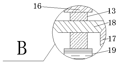
[0017] see Figure 1-3 , the present invention provides a technical solution: a technical solution of a CO2 ceramic liner welding device, including a base 1, a mounting plate 7 and a ceramic liner 11, a receiving seat 19 is fixedly installed at the middle position of the inner bottom of the base 1, and the base 1 A shaft sleeve 14 is fixedly installed at the middle position of the top, and a threaded shaft 13 is movably installed on the base 1 through a receiv...


PUM


Abstract

The invention discloses a welding device of a CO2 ceramic lining. The welding device comprises a base, a mounting plate and the ceramic lining. A bearing seat is fixedly mounted at the middle positionat the bottom end in the base. A shaft sleeve is fixedly mounted at the middle position of the top of the base. A threaded rotating shaft is movably mounted on the base through the bearing seat. Oneend of the threaded rotating shaft penetrates through the base through the shaft sleeve. A second gear is mounted at the bottom of the threaded rotating shaft in a sleeved connection manner. The second gear is located in the base. The shaft sleeve is arranged at the middle position of one side of the base. A rotating rod is movably mounted on the base through the shaft sleeve. A first gear is fixedly mounted at one end of the rotating rod and is located on one side of the second gear, and the first gear is engaged with the second gear. Through a series of structures, the device has the advantages that the ceramic lining can be conveniently fixed, and the height of the ceramic lining can be adjusted conveniently.

Description

technical field [0001] The invention relates to the field of welding technology, in particular to a CO2 ceramic liner welding device. Background technique [0002] Ceramic liner CO2 gas shielded welding single-sided welding and double-sided forming process is an efficient welding method, which has high deposition efficiency, small bevel angle, wide assembly gap, no root cleaning on the back, beautiful forming, small deformation, etc. With a series of advantages, it is more and more used in large workpieces and workpieces that cannot be turned over. [0003] In the past, all steel plate splicing welds were double-sided welding (that is, welding on both sides of the front and back), and the back side must be rooted to obtain the effect of the first-class weld of ultrasonic flaw detection, which is not only low in efficiency, but also high in cost. The single-sided welding and double-sided forming process of ceramic liner CO2 gas shielded welding is an efficient welding method...

Claims


Application Information

Patent Timeline
Patent Type & Authority Applications(China)
IPC IPC(8): B23K9/035
CPCB23K9/0352
Inventor 王新贵吴俊杰刚皓天卫合生杜传金黄国涛刘凯
Owner 鹤壁天宏钢结构有限公司
Why Eureka
Try Eureka