Magnetic resonance imaging method and magnetic resonance imaging system

A technology for magnetic resonance imaging and imaging data, applied in the field of medical devices, can solve the problems of uneven polarization effect B0 field, unable to meet clinical diagnosis needs, deviation of excitation area, etc., and achieve the effect of improving the effect of magnetic resonance imaging

Active Publication Date: 2019-09-10
SHANGHAI UNITED IMAGING HEALTHCARE
View PDF9 Cites 3 Cited by
  • Summary
  • Abstract
  • Description
  • Claims
  • Application Information

AI Technical Summary

Problems solved by technology

Since the frequency difference between related metabolites increases with the increase of the B0 field, under the limited radio frequency pulse (Radio Frequency, referred to as RF) bandwidth, as the B0 field strength increases, the chemical shift error effect (error) increases, which leads to The excitation regions of different metabolites are deviated, and the signal-to-noise ratio (SIGNAL-NOISE RATIO, referred to as SNR) of the border region is low
[0003] For this reason, the existing technology often uses high-order broadband adiabatic excitation to solve the above problems, but this solution has the problems of polarization effect and B0 field inhomogeneity, and the adiabatic Pulses need to be used in pairs, resulting in an increase in the minimum echo time (TE)
Therefore, in clinical scenarios, due to the safety limit of electromagnetic wave absorption ratio (Specific Absorption Rate, referred to as SAR) and the constraints of factors such as radio frequency transmission power and gradient performance, the minimum TE (echo time, echo time) that can finally be achieved is still relatively large , unable to meet the needs of clinical diagnosis

Method used


Image

  • Magnetic resonance imaging method and magnetic resonance imaging system
  • Magnetic resonance imaging method and magnetic resonance imaging system
  • Magnetic resonance imaging method and magnetic resonance imaging system

Examples


Embodiment 1

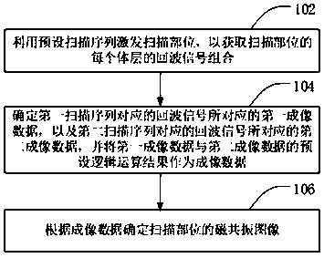
[0047] figure 1 It is a flow chart of the magnetic resonance imaging method provided by Embodiment 1 of the present invention. This embodiment is suitable for obtaining magnetic resonance imaging with a small TE, and the method can be executed by the magnetic resonance system provided by the embodiment of the present invention. The method specifically includes the following steps:

[0048] Step 102, using a preset scanning sequence to excite the scanning site, so as to obtain a combination of echo signals of each volume layer of the scanning site.

[0049]In the process of magnetic resonance imaging, the static magnetic field is usually formed by the main magnet, and then the preset scanning pulse is sent to the scanning part through the radio frequency transmitting coil based on the preset scanning sequence to excite the nuclear spin of the scanning part, and then the nuclear spin of the scanning part is obtained through the receiving coil. Echo signal combination for each s...

Embodiment 2

[0068] Figure 9 It is a schematic flowchart of a magnetic resonance imaging method provided in Embodiment 2 of the present invention. For details, see Figure 9 As shown, the method may include the following steps:

[0069] Step 202, using a preset scanning sequence to excite the scanning site, so as to obtain the echo signal combination of each volume layer of the scanning site.

[0070] Wherein, the 180-degree refocusing pulse of the first scanning sequence in the preset scanning sequence can be a conventional refocusing pulse or an adiabatic refocusing pulse. Use one or more pairs. image 3 A scan sequence diagram showing that the two 180-degree refocusing pulses of the spin echo sequence are both conventional refocusing pulses, Figure 10 It shows a scan sequence diagram of a spin echo sequence including a conventional refocusing pulse. Since only one conventional refocusing pulse is used, the time required for refocusing is reduced, thereby reducing the minimum TE; ...

Embodiment 3

[0078] Figure 14 It is a schematic structural diagram of a magnetic resonance imaging system provided by Embodiment 3 of the present invention. see Figure 14 As shown, the system includes: a scanning device 110 and an image generating device 120 . The scanning device 110 is used to transmit one or more preset scanning sequences to the scanning site in the imaging space formed with a static magnetic field to obtain the echo signal combination of each layer of the scanning site, wherein the preset scanning sequence includes Assuming that the first scanning sequence and the second scanning sequence appear in combination, the first scanning sequence includes a spin echo sequence, the second scanning sequence is a combination of an inversion recovery sequence and a spin echo sequence, and the inversion recovery pulse is used for tomography Select; the image generation device 120 is used to determine the first imaging data corresponding to the echo signals corresponding to the f...


PUM


Abstract

The invention discloses a magnetic resonance imaging method and a magnetic resonance imaging system. The method includes the following steps: a scanning portion is activated by utilizing a preset scanning sequence to obtain an echo signal combination of each of body layers of the scanning portion, wherein the preset scanning sequence includes a first scanning sequence and a second scanning sequence appearing in a preset combination, the first scanning sequence is a spin echo sequence, the second scanning sequence is a combination of an inversion recovery pulse and the spin echo sequence, and the inversion recovery pulse is used for selection of the body layers; first imaging data corresponding to an echo signal corresponding to the first scanning sequence, and second imaging data corresponding to the echo signal corresponding to the second scanning sequence are determined, and preset logical operation results of the first imaging data and the second imaging data are utilized as imagingdata; and a magnetic resonance image of the scanning portion is determined according to the imaging data. The problem that the signal-to-noise ratio of a region of interest of the scanning portion islow and minimum TE is large is solved in the prior art.

Description

technical field [0001] Embodiments of the present invention relate to medical device technology, and in particular, to a magnetic resonance imaging method and a magnetic resonance imaging system. Background technique [0002] In the pulse imaging sequence of Magnetic Resonance Imaging (MRI), there is a spectral sequence imaging, which is Magnetic Resonance Spectrum MRS (Magnetic Resonance Spectrum, MRS) imaging. MRS imaging uses the chemical shift difference of metabolites to obtain metabolite information , by analyzing metabolic activity to obtain changes in the level of relevant metabolites. Since the frequency difference between related metabolites increases with the increase of the B0 field, under the limited radio frequency pulse (Radio Frequency, referred to as RF) bandwidth, as the B0 field strength increases, the chemical shift error effect (error) increases, which leads to The excitation regions of different metabolites are biased, and the signal-to-noise ratio (SI...

Claims


Application Information

Patent Timeline
IPC IPC(8): A61B5/055
CPCA61B5/055
Inventor 温林飞
Owner SHANGHAI UNITED IMAGING HEALTHCARE
Why Eureka
Try Eureka