
Combined ball valve element

A combined, spherical valve core technology, applied in valve details, valve devices, valve devices for absorbing fluid energy, etc., can solve the problem of low adjustment accuracy of circular through-hole valve cores, short valve service life, and easy erosion. and other problems, to avoid cavitation and high-speed media erosion, improve service life, and have a wide range of applications.

Pending Publication Date: 2019-09-06
HARBIN HBC VALVE
View PDF0 Cites 0 Cited by
  • Summary
  • Abstract
  • Description
  • Claims
  • Application Information

AI Technical Summary

Problems solved by technology

The adjustment accuracy of the circular through-hole spool is low; the "V"-shaped spool has a high adjustment accuracy for liquid media, but the adjustment effect for steam media is not ideal, especially in the case of high-pressure differential media, which is prone to erosion; Throttle small hole + throttle orifice combined valve core is only suitable for high pressure differential conditions
However, at present, thermal power, nuclear power, and petrochemical equipment have working conditions where small flow and high pressure difference coexist, and large flow and small pressure difference coexist. The spool is not suitable for the above complex working conditions
Under the condition of high pressure difference, the "V"-shaped valve core and the circular through-hole valve core are prone to erosion, and the service life of the valve is short; the throttle hole + throttle orifice combined valve core is not suitable for large flow and small pressure difference Working conditions, the flow capacity of the spool is insufficient

Method used


Image

  • Combined ball valve element
  • Combined ball valve element
  • Combined ball valve element

Examples


Embodiment Construction

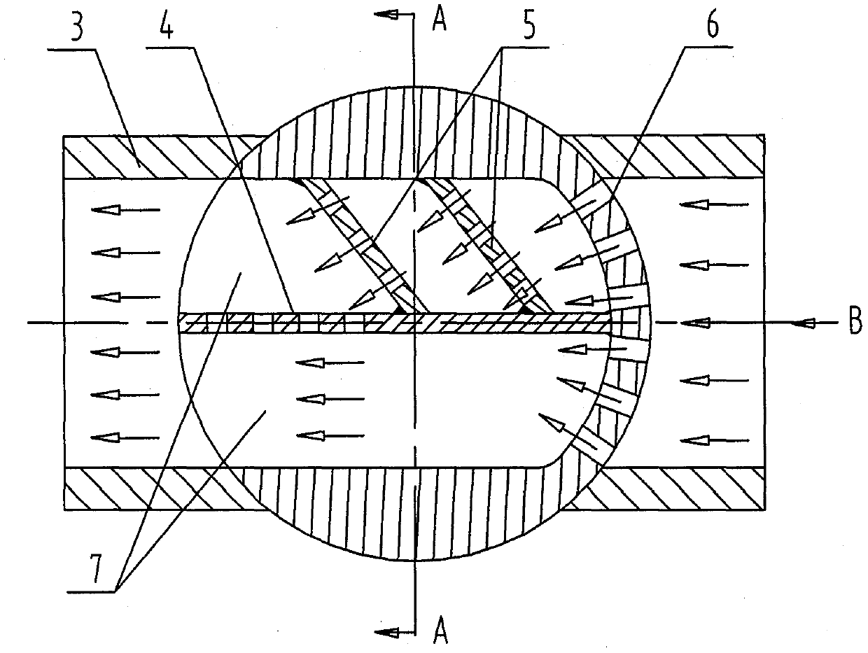
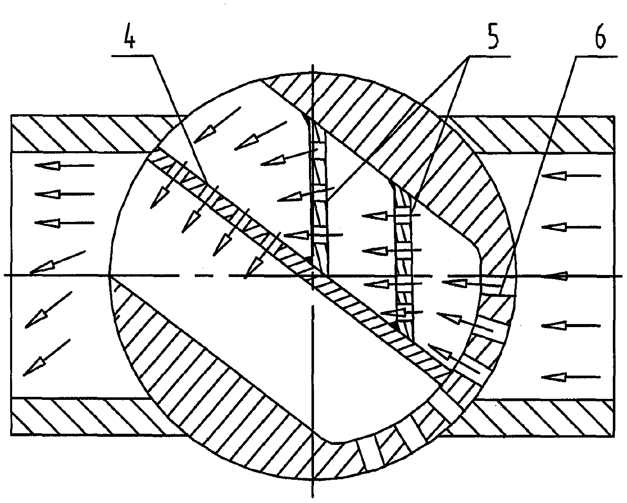
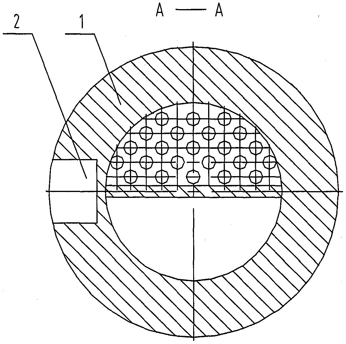
[0013] Such as figure 1 , figure 2 , image 3 , Figure 4 , Figure 5 , Figure 6 As shown, the present invention includes a spherical valve core body (1), a valve seat (3), an A-type throttle orifice (4), a B-type throttle orifice (5), a spherical adjustment pair (6), a circular channel (7) etc. The middle part of the spherical valve core body (1) is a circular channel (7), and one side of the channel is a small-hole spherical surface adjustment pair. In the circular channel of the valve core body, a piece of A-shaped throttle orifice is arranged along the direction of the flow channel. Type A throttling orifice is only processed with throttling holes in the lower half; one or more B-type throttling orifices are set in the upper space between the A-type throttling orifice and the circular channel, and no throttling holes are set in the lower space plate. Through the valve stem interface (2), the spherical valve core body (1) is connected with the valve stem, and the v...


PUM


Abstract

The invention relates to a combined ball valve element. The combined ball valve element comprises a spherical valve element body and orifice plates. The top end of the valve element body is a valve stem joint, the middle part of the valve element body is a circular passage, one side of the passage is a small-hole spherical adjustment pair, and one orifice plate is arranged along the flow path in the circular passage of the valve element body. Throttle holes are formed in the lower portions of the orifice plates. One or more orifice plates are arranged in the upper space of the orifice plate and the circular passage, and no orifice plates are arranged in the lower space. The valve element is suitable for both small flow and high pressure differential conditions as well as for large flow andsmall differential pressure conditions, and a valve has a wide application range.

Description

technical field [0001] The invention relates to a combined ball valve core, which is suitable for working conditions where small flow and high pressure difference coexist with large flow and small pressure difference, and is used for ball valves in thermal power, nuclear power and petrochemical fields. Background technique [0002] The existing spools for ball valves with adjustable flow rate are "V"-shaped spools, small throttle holes + throttle orifice combined spools or circular through-hole spools. The adjustment accuracy of the circular through-hole spool is low; the "V"-shaped spool has a high adjustment accuracy for liquid media, but the adjustment effect for steam media is not ideal, especially in the case of high-pressure differential media, which is prone to erosion; The throttle hole + throttle orifice combined valve core is only suitable for high pressure differential conditions. However, at present, thermal power, nuclear power, and petrochemical equipment have...

Claims


Application Information

Patent Timeline
IPC IPC(8): F16K5/06F16K5/08F16K5/10F16K5/12F16K47/04
CPCF16K5/0605F16K5/08F16K5/10F16K5/12F16K47/045
Inventor 万胜军高德明王明毛健
Owner HARBIN HBC VALVE
Learn More