Mobile fabricated beam erection system for support method beam splicing of prefabricated segmental beams

A support system and assembly technology, applied in the erection/assembly of bridges, bridges, bridge construction, etc., can solve the problems of low efficiency, high requirements on beam alignment accuracy, and high equipment dependence.

Pending Publication Date: 2019-09-06
中铁八局集团第二工程有限公司 +1
View PDF0 Cites 3 Cited by
  • Summary
  • Abstract
  • Description
  • Claims
  • Application Information

AI Technical Summary

Problems solved by technology

[0002] The use of bridge erecting frame girders includes the placement of bridge erecting machines, lifting beams, gluing, temporary tensioning, wet joint construction, external prestressed tensioning, and passing holes; the construction period is generally 6-7 days. The equipment is highly dependent. In bad weather such as rain and snow, the wet joint strength cannot meet the construction conditions on time, which affects the construction period. Night construction is more dangerous
Therefore, it is necessary to use the bracket method to erect the beam, but the existing prefabricated beam erection system for the bracket method is not mature enough, making the efficiency low
[0003] In the process of splicing beams by the bracket method, since the beam body is divided into several segments, several segments need to be assembled into a whole during construction. In this process, splicing glue needs to be applied, and there is a 30cm reserved seam between the beam bodies. At this time, it is necessary Segmental beams slip in a small range, and the alignment accuracy of the beams is too high during gluing. At this time, it is necessary to fine-tune the elevation after the alignment of the beams is completed. , the existing technology cannot solve this kind of problem very well

Method used


Image

  • Mobile fabricated beam erection system for support method beam splicing of prefabricated segmental beams
  • Mobile fabricated beam erection system for support method beam splicing of prefabricated segmental beams
  • Mobile fabricated beam erection system for support method beam splicing of prefabricated segmental beams

Examples


Embodiment 1

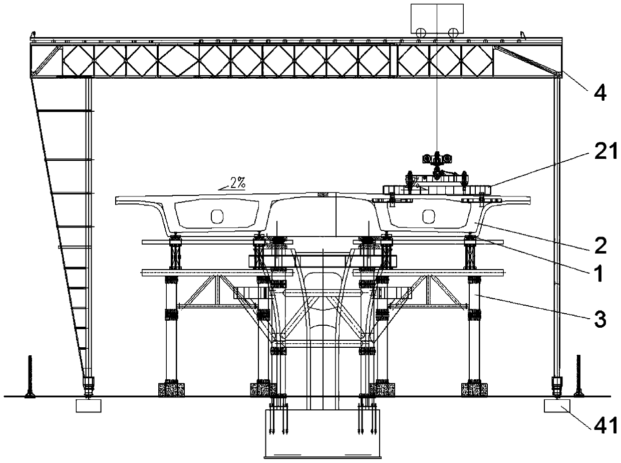
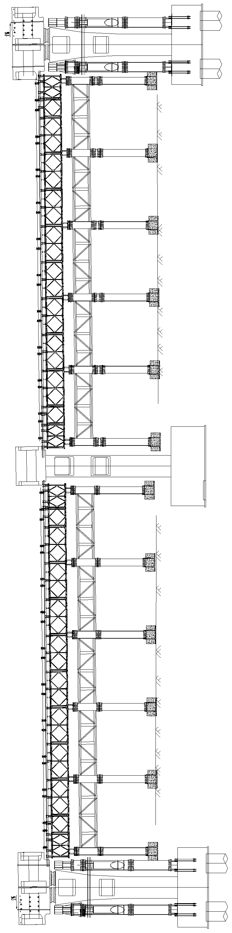
[0041] Example 1, such as Figure 1-4 shown;

[0042] A mobile assembly beam erecting system for prefabricated segmental beam support method, including:

[0043] The gantry crane track foundation 41; the gantry crane track foundation 41 is poured on the ground on both sides of the pier and made, and a gantry crane track (not shown) is installed on each gantry crane track foundation 41;

[0044] Gantry Crane 4; Gantry Crane 4 is removably installed on the Gantry Crane track;

[0045] A spreader 21 for hoisting the beam 2; the spreader 21 is movably installed on the gantry crane 4;

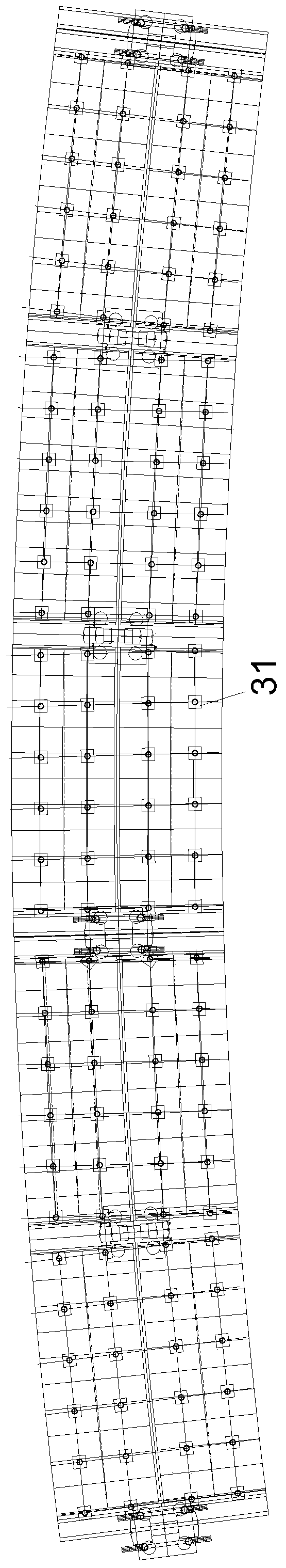
[0046] Support system 3; support system 3 is installed on both sides of the pier;

[0047] Steel rail 5; multiple steel rails 5 are installed on the top of support system 3;

[0048] The sliding wire top 1; the beam 2 is placed on a plurality of sliding wire tops 1, and each sliding wire top 1 slides on a steel rail 5 correspondingly.

[0049] The rated lifting capacity of the gantry crane 4 is...

Embodiment 2

[0052] Example 2, such as Figure 5-11 shown;

[0053] The difference between this embodiment and Embodiment 1 is that the sliding wire top 1 includes:

[0054] The wire head 11; the lower end of the wire head 11 is provided with a spherical groove, and the beam 2 is placed on the top of the wire head 11;

[0055] Chuck 12;

[0056] Screw mandrel 13; the top of screw mandrel 13 is formed as outwardly protruding spherical structure 131, and spherical structure 131 is nested in the spherical groove and is formed as a rotatable movable head; The spherical structure 131 bottom of screw mandrel 13 is formed with Disc notch 132, the chuck 12 is set on the chuck notch 132, the upper end of the chuck 12 is fixedly connected with the bottom of the wire head 11, and the size of the chuck 12 is used to prevent the movable head from disengaging; An adjustment hole 133 for adjusting the horizontal height of the screw mandrel 13 is formed on the screw mandrel 13 below the 132; an outer w...

Embodiment 3

[0074] Example 3, such as Figure 10 shown;

[0075] The difference between this embodiment and Embodiment 2 is that the chuck 12 includes a first sub-chuck 121 and a second sub-chuck 122, the first sub-chuck 121 and the second sub-chuck 122 have the same shape, and the first sub-chuck Both the disk 121 and the second sub-chuck 122 are provided with a semicircular notch 141 on one side, and the side of the first sub-chuck 121 provided with the semicircular notch 141 and the side of the second sub-chuck 122 are provided with a semicircular notch. One side of the notch 141 is butted, and the chuck notch 132 is surrounded in the middle, and the radius of the round hole surrounded by the first sub-chuck 121 and the second sub-chuck 122 is smaller than the radius of the spherical structure 131 and the radius of the spherical groove .


PUM


Abstract

The invention discloses a mobile fabricated beam erection system for support method beam splicing of prefabricated segmental beams. The mobile fabricated beam erection system comprises gantry crane track foundations, a gantry crane, a lifting device for lifting the beams, a support system, steel rails and slipping wire jacks. According to the mobile fabricated beam erection system for support method beam splicing of the prefabricated segmental beams, positioning of the segmental beams can be quickly and effectively adjusted through the combination of "gantry crane + lifting device", and quicksupport removal can be performed through the slipping wire jacks; the slipping wire jacks, the steel rails and the support system together form a slipping system, and movement of beam bodies in trackscan be completed through temporary tensioning; a rotatable movable head is arranged to enable the mobile fabricated beam erection system to be adapted to the slope of different beams through rotation; a lifting system is formed by screw rods, screw rod sleeving heads and clamping boards, and the elevation of the beams can be controlled by adjusting the length, protruding above the screw head sleeving heads, of the screw rods; through the special structures of the slipping wire jacks, the time consumed by wet joint construction and external prestress tensioning can be saved, less dependence onequipment is achieved, and a plurality of working faces can be arranged at the same time.

Description

technical field [0001] The invention belongs to the technical field of assembly of prefabricated segmental beams, and in particular relates to a mobile assembly type beam erecting system used for prefabricated segmental beam brackets. Background technique [0002] The use of bridge erecting frame girders includes the placement of bridge erecting machines, lifting beams, gluing, temporary tensioning, wet joint construction, external prestressed tensioning, and passing holes; the construction period is generally 6-7 days. The equipment is highly dependent. In severe weather such as rain and snow, the wet joint strength cannot meet the construction conditions on time, which affects the construction period, and night construction is more dangerous. Therefore, it is necessary to use the bracket method to erect the beam, but the existing prefabricated beam erection system for the bracket method is not mature enough, which makes the efficiency low. [0003] In the process of splic...

Claims


Application Information

Patent Timeline
Patent Type & Authority Applications(China)
IPC IPC(8): E01D21/00
CPCE01D21/00
Inventor 杨宇何天贵雷成龙谢阳福高军黄鹏月陆浩祥余骏谭俊蒋德海
Owner 中铁八局集团第二工程有限公司
Why Eureka
Try Eureka