
Electric power assisted braking system

A brake system and electric power assist technology, which is applied in the direction of brakes, brake transmission devices, transportation and packaging, etc., can solve the problems of too deep trampling, high cost, and high requirements for installation positions, so as to save costs and improve applicability Effect

Pending Publication Date: 2019-09-06
WANXIANGQIANCHAO CO LTD +1
View PDF10 Cites 2 Cited by
  • Summary
  • Abstract
  • Description
  • Claims
  • Application Information

AI Technical Summary

Problems solved by technology

[0003] The existing technical solutions mainly have the following disadvantages: the brake system of the Honda hybrid vehicle adopts the method of dual brake master cylinders to realize the function, the cost is high, and the requirements for the installation position are relatively high; Bosch adopts the method of ibooster+esc hev to realize the function , the two must be used together to achieve the corresponding function, which limits the application of the product; Nason uses the empty stroke to realize the function of energy recovery, but when it fails, it will step on it too deeply, causing users to panic

Method used


Image

  • Electric power assisted braking system
  • Electric power assisted braking system
  • Electric power assisted braking system

Examples


Embodiment

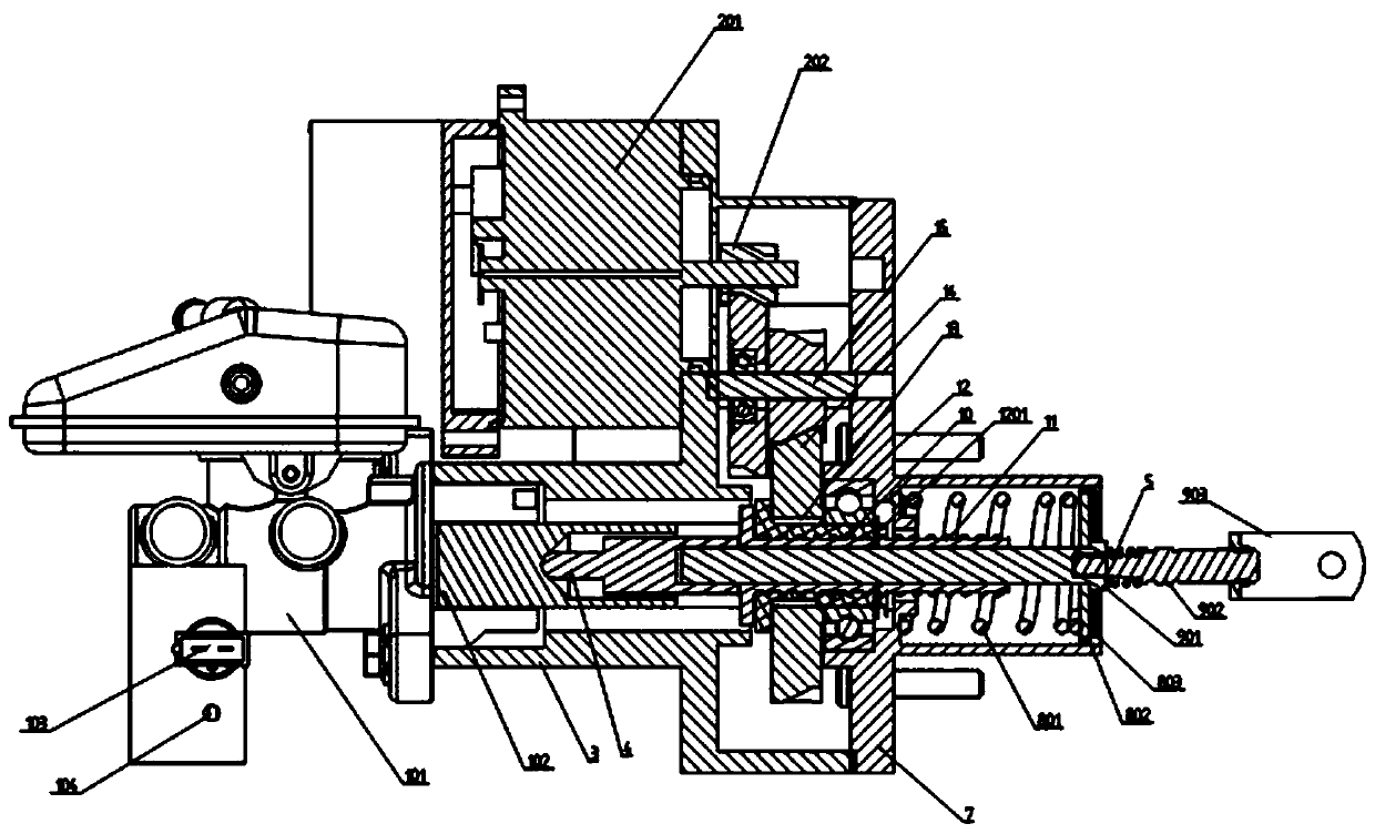
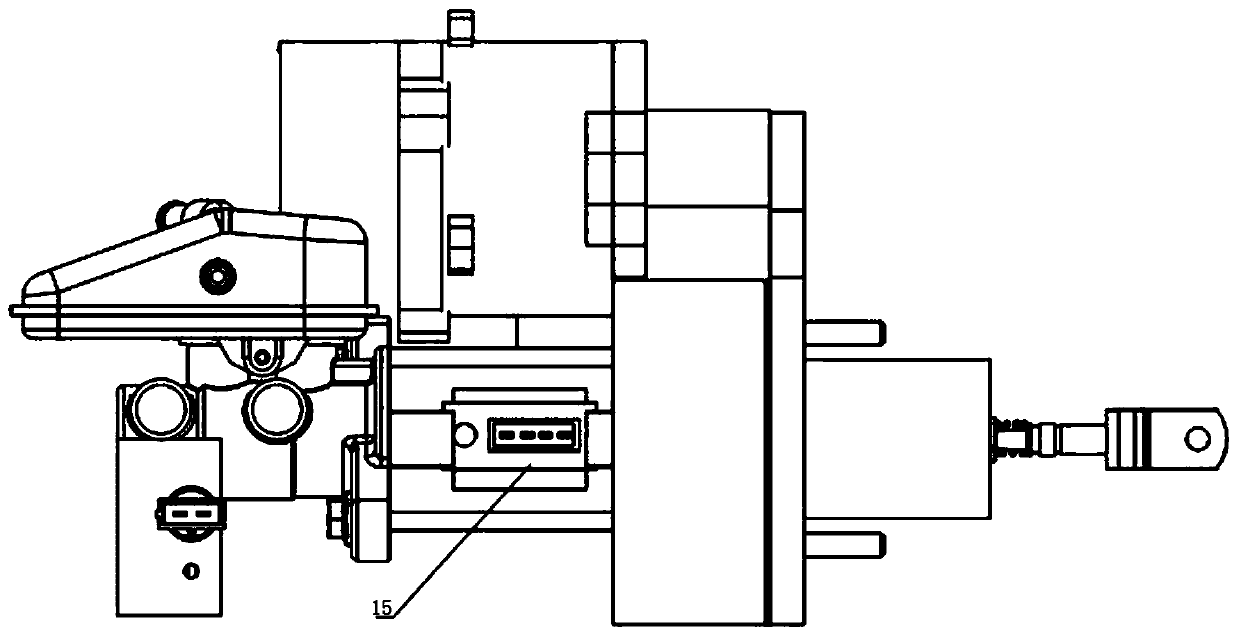
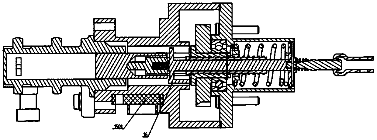
[0019] Example: As shown in the attached drawings, this electric power brake system mainly includes a master brake cylinder block 101, a master brake cylinder piston 102, a solenoid valve 103, a liquid storage chamber 104, a motor 201, a gear 202, a box Body 3, output rod 4, upper cover 7, push rod 901, input rod 902, shift fork 903, nut 10, screw rod 11, bearing 12, collar 1201, flat key 13, gear pair 14, sensor 15, sensor The chip 1501, the magnetic body 16, and the output shaft of the motor 201 are connected to the gear 202. The gear 202 transmits torque to the nut 10 through the gear pair 14. The gear pair 14 and the nut 10 are connected by a flat key 13. The nut 10 is installed on On the bearing 12 to realize positioning and rotation, one end of the nut 10 is limited by the clamp ring 1201, and the nut 10 is matched with the connecting screw 11 to convert the torque transmitted by the gear pair 14 into thrust and act on the output rod 4 at one end of the screw 11. , the o...


PUM


Abstract

The invention discloses an electric power assisted braking system. The electric power assisted braking system comprises a brake master cylinder body and the like. A motor transmits torque to a nut through a gear pair, the nut is internally connected with a screw rod in a matched mode to convert the torque transmitted by the gear pair into thrust, the thrust is applied to a force output rod at oneend of the screw rod, and the force output rod transmits the thrust to a brake master cylinder piston at one end to generate the hydraulic pressure required for braking; one end of a pushing fork is connected with a pedal to obtain input intention, and the other end of the pushing fork is connected with an input rod to transmit the input intention and the input force; and an push rod is connectedwith an input rod, a magnetic body is connected with the push rod to reflect the change of input displacement, and a the sensor chip is installed in a sensor to output the displacement change of the magnetic body. According to the electric power assisted braking system, the electric power assisted braking of a vehicle is realized, and the electric power assisted braking system is matched with thewhole vehicle to carry out relevant energy recovery without the support of ESC; the whole energy recovery process becomes controllable, and the energy recovery process can be intervened at any time according to requirements; and it is ensured that the consistency of foot feeling in the whole process can be ensured under various conditions.

Description

technical field [0001] The invention relates to the field of braking systems, in particular to an electric power-assisted braking system. Background technique [0002] At present, the electric power assist systems used in the market mainly include: Honda hybrid vehicle braking system, which uses a dual-brake master cylinder to achieve its functions; Bosch uses ibooster+esc hev to achieve its functions; Nassen uses an empty stroke method to achieve braking energy recovery. [0003] The existing technical solutions mainly have the following disadvantages: the Honda hybrid vehicle braking system adopts the method of dual brake master cylinders to realize the function, the cost is high, and the installation position is relatively high; Bosch adopts the method of ibooster+esc hev to realize the function. , the two must be used together to achieve the corresponding function, which limits the application of the product; Nassen uses the empty stroke method to achieve the function o...

Claims


Application Information

Patent Timeline
Patent Type & Authority Applications(China)
IPC IPC(8): B60T13/74B60T13/68
CPCB60T13/745B60T13/686
Inventor 任博林国贤滕瑞静王勇宋敬涛
Owner WANXIANGQIANCHAO CO LTD
Learn More