Mold core for manufacturing light guide plate and microstructural manufacturing method of mold core

A manufacturing method and microstructure technology, applied in applications, home appliances, optical components, etc., can solve the problems of consumption, excessive production costs and man-hours, and the nickel layer is easily damaged, and achieve the effect of improving assembly accuracy

Active Publication Date: 2019-09-06
YANGXIN TECH SUZHOU
View PDF6 Cites 4 Cited by
  • Summary
  • Abstract
  • Description
  • Claims
  • Application Information

AI Technical Summary

Problems solved by technology

However, when designing the local microstructure of the mold core, the entire mold core needs to be nickel-plated before processing. The large-area nickel layer is easily damaged during production, and maintenance needs to be completely reprocessed, which consumes more production costs and man-hours.

Method used


Image

  • Mold core for manufacturing light guide plate and microstructural manufacturing method of mold core
  • Mold core for manufacturing light guide plate and microstructural manufacturing method of mold core
  • Mold core for manufacturing light guide plate and microstructural manufacturing method of mold core

Examples


Embodiment Construction

[0016] The foregoing and other technical contents, features and effects of the present invention will be clearly presented in the following detailed description of an embodiment with reference to the accompanying drawings. The directional terms mentioned in the following embodiments, such as: up, down, left, right, front or back, etc., are only directions referring to the attached drawings. Accordingly, the directional terms are used to illustrate and not to limit the invention.

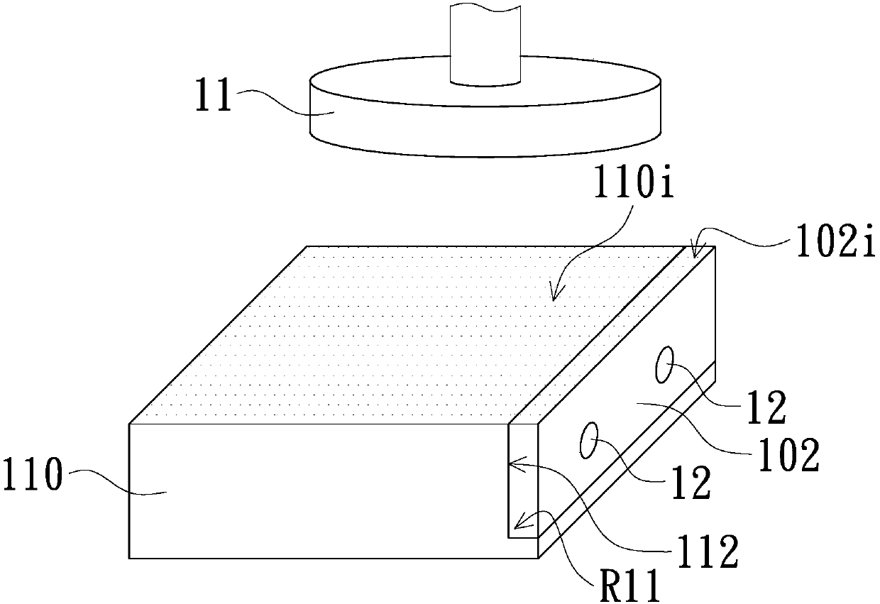
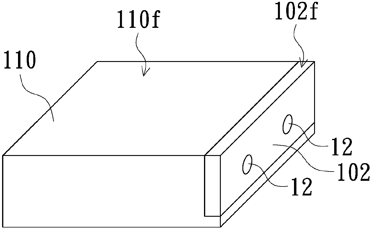
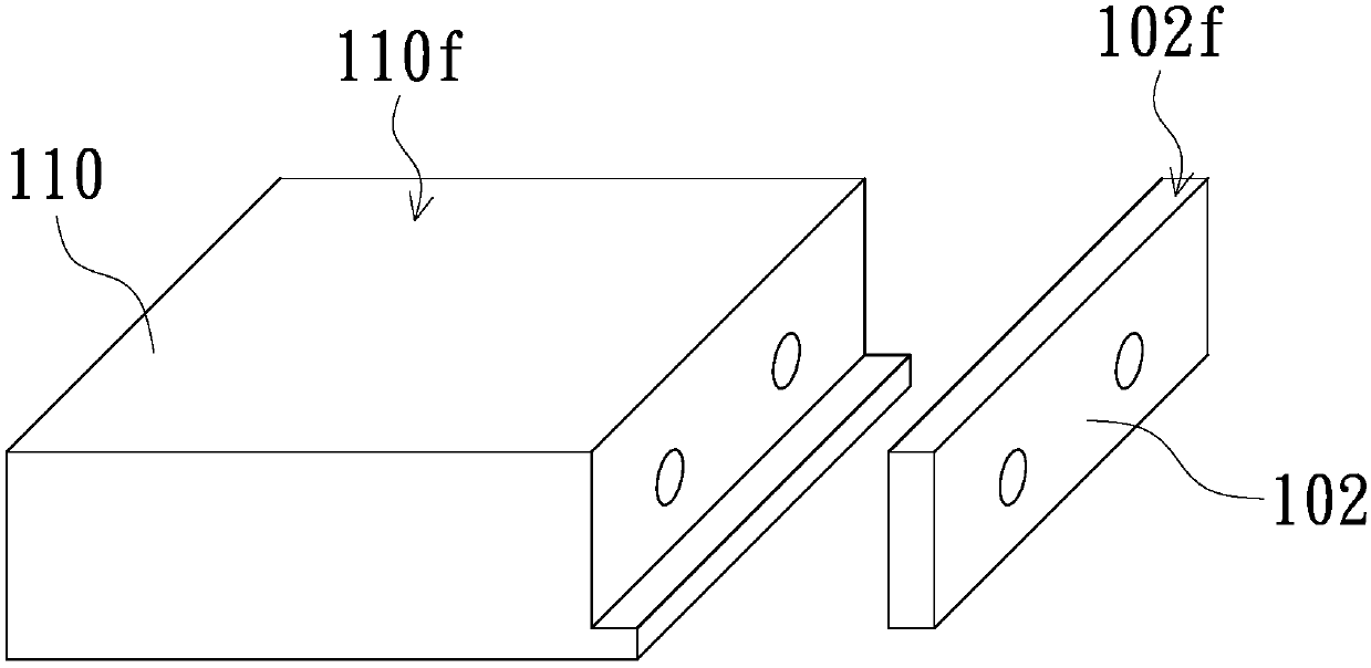
[0017] Figure 1A to Figure 1H It is a three-dimensional schematic view of the manufacturing method of the mold core microstructure in an embodiment of the present invention. see Figure 1A , in the microstructure manufacturing method of the mold core in this embodiment, firstly, the mold core body 110 and the alignment insert 102 are provided, and the alignment insert 102 is mounted on the mold core body 110 . by Figure 1A For example, the alignment insert 102 can be connected by at least one s...


PUM


Abstract

A microstructural manufacturing method of a mold core comprises the following steps that an aligned insert is mounted on a mold core body; then the aligned insert and the mold core body are subjectedto mirror polishing, so that a datum plane is formed by the aligned insert, and a polished face is formed by the mold core body, wherein the datum plane and the polished face are cut flush; after thealigned insert and the mold core body are subjected to mirror polishing, the aligned insert and the mold core body are separated; then the aligned insert and a processed insert are fixed to the horizontal plane, wherein the bottom face of the aligned insert and the bottom face of the processed insert are both located on the horizontal plane; then the processed insert is planed to form a smooth face, wherein the height of the smooth face relative to the horizontal plane is substantially equal to the height of the datum plane relative to the horizontal plane; and then the processed insert is cutfrom the smooth face to form a microstructural insert. In addition, the mold core is provided.

Description

technical field [0001] The present invention relates to a tool for manufacturing a light guide plate and a method for manufacturing a light guide plate, and in particular to a mold core for manufacturing a light guide plate and its microstructure. method. Background technique [0002] A light guide plate is an existing common optical element, which can be used as a surface light source capable of emitting light uniformly, and the existing light guide plate is usually used in liquid crystal displays and lamps. There are usually microstructures on the surface of the light guide plate, which can scatter light, so that the light transmitted in the light guide plate can exit from the light-emitting surface of the light guide plate. The current light guide plate has been made by mold core, and the microstructure can also be formed by mold core. The above-mentioned microstructure can influence the optical performance of the light guide plate, so the mold core used to manufacture ...

Claims


Application Information

Patent Timeline
Patent Type & Authority Applications(China)
IPC IPC(8): B29C33/38B29C33/42B29L11/00
CPCB29C33/3842B29C33/42B29L2011/0075
Inventor 史常青夏启李炎阳邱良芳
Owner YANGXIN TECH SUZHOU
Why Eureka
Try Eureka