
Aircraft engine tail spray disassembling auxiliary tool

An aircraft engine and auxiliary tooling technology, applied in the field of aircraft maintenance, can solve problems such as tool and component damage, seizure, body injury, etc., and achieve the effect of simple operation and uniform force

Pending Publication Date: 2019-09-06
SHANDONG TAIKOO AIRCRAFT ENG
View PDF0 Cites 3 Cited by
  • Summary
  • Abstract
  • Description
  • Claims
  • Application Information

AI Technical Summary

Problems solved by technology

[0002] The maintenance of the aircraft engine is the top priority for the safety of the aircraft. For the convenience of aircraft maintenance, it is often necessary to remove the engine tail nozzle for internal inspection or replace related parts. Most of the Boeing 737 series aircraft engine tail nozzle configuration The tail nozzle is fixed on the tail nozzle by bolts. Since the tail nozzle and the tail nozzle are in the high-low temperature fusion, high-frequency vibration and contact area of ​​various liquids at the tail of the engine, the connection between the bolt and the tail nozzle and the tail nozzle occurs. Stress changes, which will lead to a "seizure" situation when the connecting bolts are removed. Under the existing removal method, it is likely to cause damage to the fasteners, which further leads to the failure to remove them smoothly. There are 24 fastening screws in total, evenly distributed At the end of the tail nozzle, when removing the 24 bolts, it is necessary to exert greater pressure on the fasteners that appear to be "seized", so the body will be injured in the morning due to the excessive force of the staff during the removal.
Conventional removal of damaged fasteners such as nail remover removal, drilling removal and other methods are not applicable. The existing nail remover is not suitable for the configuration of the engine tail nozzle. Forced use will easily cause damage to tools and components. Drilling removal is very important for the engine The core components are easy to cause damage, and if damage occurs, the removal of the tail nozzle will be very difficult

Method used


Image

  • Aircraft engine tail spray disassembling auxiliary tool
  • Aircraft engine tail spray disassembling auxiliary tool

Examples


Embodiment Construction

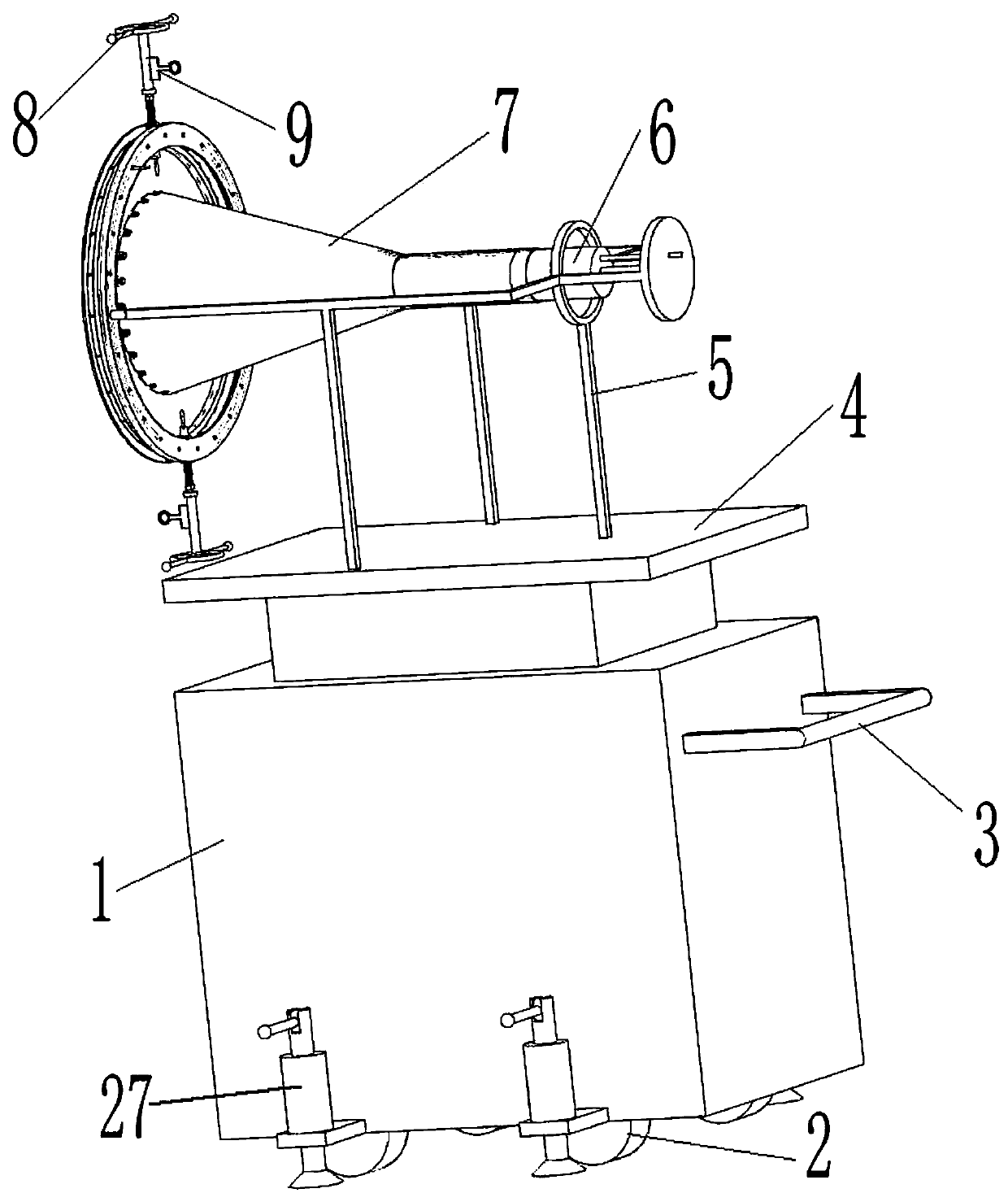
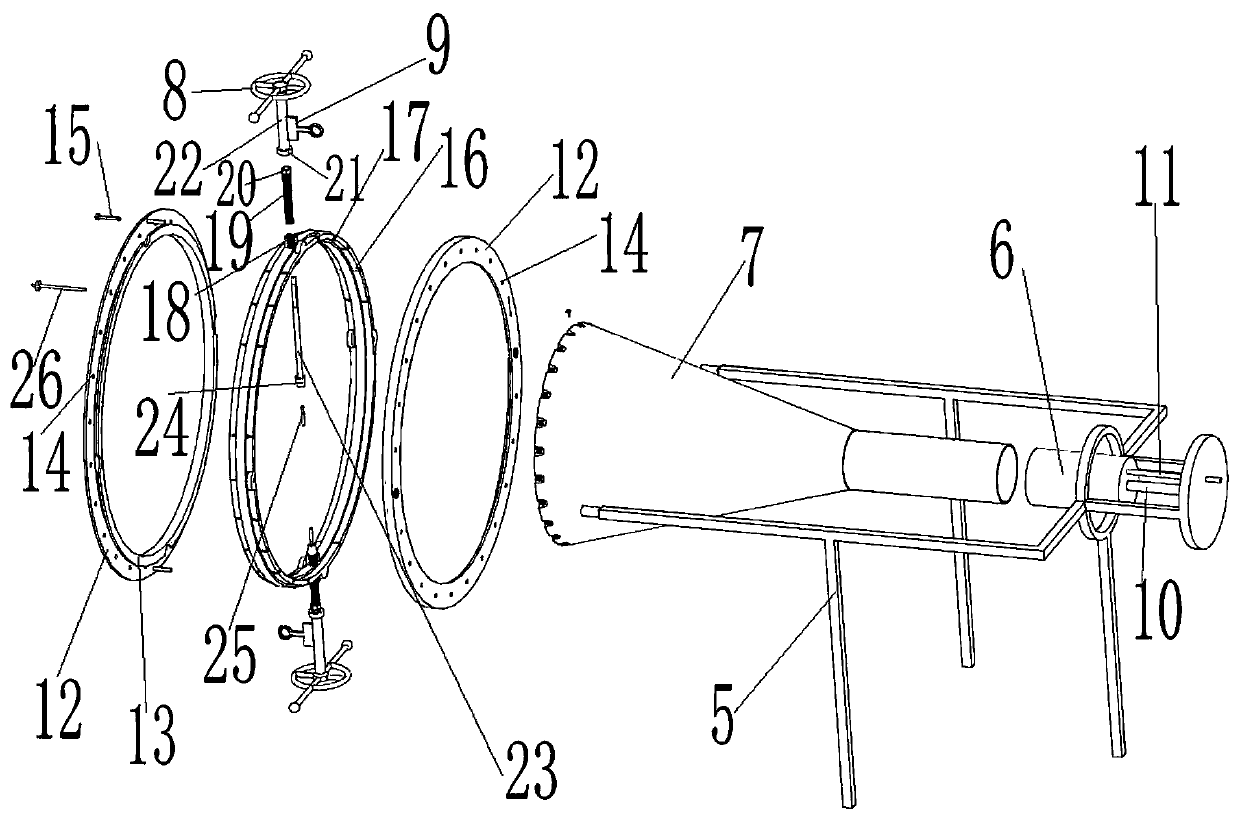
[0022] Attached below figure 1 , attached figure 2 The present invention will be further described.

[0023] An auxiliary tool for aircraft engine tail spray removal, comprising: a hydraulic lifting platform 1, a support 5 is installed on the lifting platform 4; , the centering column 6 is coaxial with the guide rail 10, the outer diameter of the centering column 6 matches the diameter of the inner hole at the front end of the tail nozzle 7, and the centering column 6 is inserted into the inner hole at the front end of the tail nozzle 7; the rotating guide mechanism, Installed on the rear end of the bracket 5, the circular swivel 16 is rotatably installed in the rotation guide mechanism, the swivel 16 is coaxial with the centering column 6, the tail nozzle 7 is located in the inner hole of the swivel 16, and the swivel 16 The upper and lower ends are respectively vertically provided with an actuating rod 23, the inner end of the actuating rod 23 is provided with a cutter he...


PUM


Abstract

The invention relates to an aircraft engine tail spray disassembling auxiliary tool. A centering column moves towards the inner side along a guide rail and is inserted into an inner hole in the frontend of a tail spray nozzle, the tail end of the tail spray nozzle is located in conversion, a steering guiding mechanism enables a rotating ring to rotate to the appropriate position and is locked through a positioning mechanism, then actuating levers are driven by an actuating lever drive mechanism to move towards the inner side, cutter heads at the inner side ends of the actuating levers are inserted into corresponding fixing screws, and the fixing screws can be loosened by rotating the actuating levers. Since the two sets of symmetrical actuating levers are arranged, simultaneous removal action in the up and down direction can be achieved, and stress of the tail spray nozzle is even. All fixing screws on the tail spray nozzle are disassembled by continuously rotating the rotating ring.The overall process is simple in operation, aircraft components cannot be damaged, and injuries on an operator can be avoided.

Description

technical field [0001] The invention relates to the technical field of aircraft maintenance, in particular to an auxiliary tool for dismantling the tail spray of an aircraft engine. Background technique [0002] The maintenance of the aircraft engine is the top priority for the safety of the aircraft. For the convenience of aircraft maintenance, it is often necessary to remove the engine tail nozzle for internal inspection or replace related parts. Most of the Boeing 737 series aircraft engine tail nozzle configuration The tail nozzle is fixed on the tail nozzle by bolts. Since the tail nozzle and the tail nozzle are in the high-low temperature fusion, high-frequency vibration and contact area of ​​various liquids at the tail of the engine, the connection between the bolt and the tail nozzle and the tail nozzle occurs. Stress changes, which will lead to a "seizure" situation when the connecting bolts are removed. Under the existing removal method, it is likely to cause damag...

Claims


Application Information

Patent Timeline
Patent Type & Authority Applications(China)
IPC IPC(8): B25B27/14
CPCB25B27/14
Inventor 顾辉张伟光郭怀超
Owner SHANDONG TAIKOO AIRCRAFT ENG
Learn More