
Clutch housing intelligent machining forming production line

A clutch housing, processing and forming technology, applied in metal processing, manufacturing tools, other manufacturing equipment/tools, etc., can solve the problems of high manual handling costs, complex drive structure, and bulky volume, etc., to achieve convenient control and high production efficiency , the effect of small footprint

Pending Publication Date: 2019-09-06
ZHONGSHAN XINHUI PRECISION TECH CO LTD
View PDF0 Cites 2 Cited by
  • Summary
  • Abstract
  • Description
  • Claims
  • Application Information

AI Technical Summary

Problems solved by technology

During processing and production, the clutch shell blank is usually trimmed on the cutting machine, the bowl edge of the blank shell is cut off, and a semi-finished product that meets the height dimension is processed, and then the cooling holes are punched on the punching machine and punched on the tongue table. The punching and cutting tongue table is carried out on the device, and among the above-mentioned several different stations, it is necessary to collect the semi-finished products on the handling trolley after each station, and then manually transport them to another station for processing and production, while the punching machine The tongue table punching device is usually driven by hydraulic pressure, the driving structure is complex, the volume is huge, the machines in different processing stations are scattered, and the cost of manual handling is high

Method used


Image

  • Clutch housing intelligent machining forming production line
  • Clutch housing intelligent machining forming production line
  • Clutch housing intelligent machining forming production line

Examples


Embodiment Construction

[0038] The present invention will be further described below in conjunction with accompanying drawing:

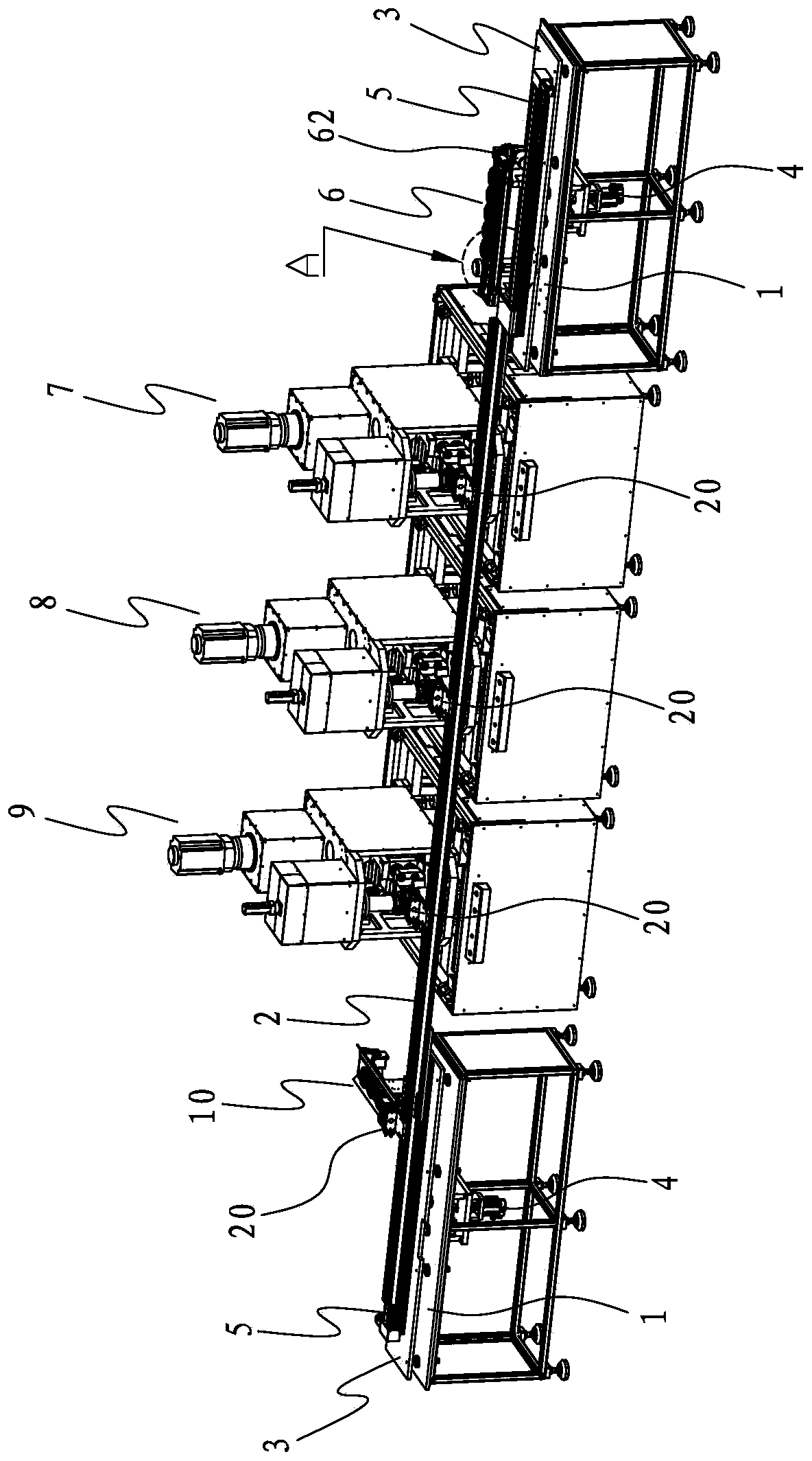
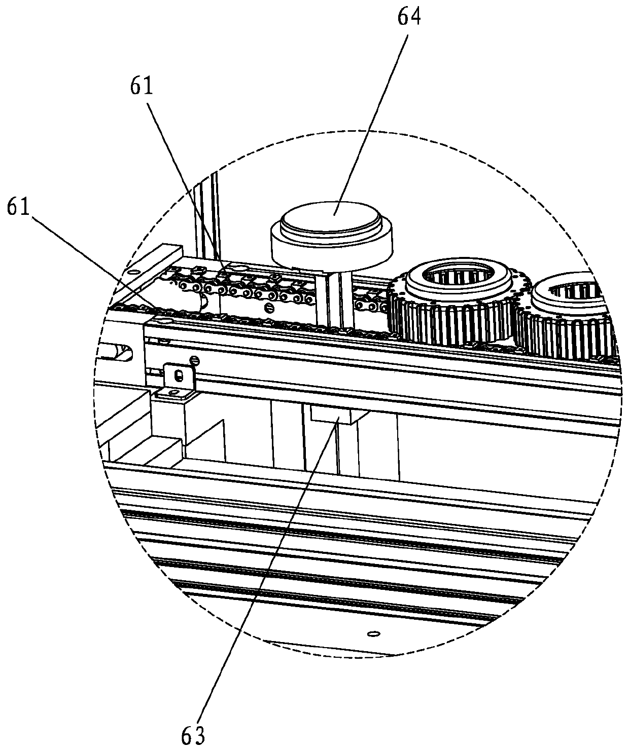
[0039] Such as Figure 2 to Figure 15 A production line for intelligently processing and forming clutch housings is shown, which includes two workbenches 1 separated on the left and right. Lifting plates 3 are slidably connected to the workbenches 1, and the bottom of the workbench 1 is provided with a The lifting cylinder 4 for lifting the plate 3, the feeding conveyor line 6 is provided on the right table 1, and the discharging conveyor line 10 is provided on the left table 1, and the distance between the two table 1 is from right to left A trimming device 7, a punching device 8 and a punching tongue device 9 are provided at intervals in sequence, the trimming device 7 is used for punching the bowl edge of the blank shell to a fixed length, and the punching device 8 is used for punching cooling holes 101, the punching tongue device 9 is used for punching and cutting the ...


PUM


Abstract

The invention discloses a clutch housing intelligent machining forming production line. The clutch housing intelligent machining forming production line comprises a left working table and a right working table. Lifting plates capable of ascending and descending are slidably connected to the working tables. A feeding conveying line is arranged on the working table on the right side. A discharging conveying line is arranged on the working table on the left side. An edge cutting device, a punching device and a tongue punching device are arranged between the two working tables from right to left in sequence. A conveying rod is slidably connected between the two lifting plates. The conveying rod is driven to move left and right through linear sliding tables. The feeding conveying line, the edgecutting device, the punching device, the tongue punching device and the discharging conveying line are arranged on the same side and arranged equidistantly. Four clamping devices arranged equidistantly are fixed to the conveying rod. The clamping devices are used for clamping clutch housings and are driven by the linear sliding tables to transfer the clutch housings between the feeding conveyingline, the edge cutting device, the punching device, the tongue punching device and the discharging conveying line front and back. The clutch housing intelligent machining forming production line achieves the effects of automatic feeding, fixed-length cutting, punching, tongue punching and discharging.

Description

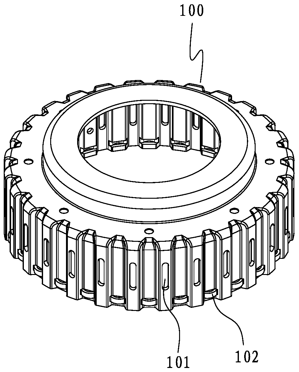
[0001] 【Technical field】 [0002] The invention relates to the field of mechanical intelligent processing, in particular to a production line for intelligently processing and forming clutch housings. [0003] 【Background technique】 [0004] In the automobile manufacturing industry, the processing of the clutch is relatively complicated. In the prior art, multiple clamping is required to process different parts. Such as figure 1 As shown, it is a clutch housing 100, which has a bowl-shaped structure as a whole, and its side is uniformly provided with cooling holes 101 and tongue platforms 102 along the circumferential direction. During processing and production, the clutch shell blank is usually trimmed on the cutting machine, the bowl edge of the blank shell is cut off, and a semi-finished product that meets the height dimension is processed, and then the cooling holes are punched on the punching machine and punched on the tongue table. The punching and cutting tongue table i...

Claims


Application Information

Patent Timeline
Patent Type & Authority Applications(China)
IPC IPC(8): B23P23/06B23Q7/14
CPCB23P23/06B23Q7/1415
Inventor 李祥军李稷肖纪春何文胜夏炎
Owner ZHONGSHAN XINHUI PRECISION TECH CO LTD
Learn More