Self-locking drawbar and draw-bar box

A self-locking, tie-rod technology, applied in travel goods, applications, clothing, etc., can solve the problems of complex structure and production process, and many parts of the tie-rod structure, so as to enhance the overall design sense of appearance, simple structure and simplified production process Effect

Inactive Publication Date: 2019-09-06
曾冰
View PDF0 Cites 1 Cited by
  • Summary
  • Abstract
  • Description
  • Claims
  • Application Information

AI Technical Summary

Problems solved by technology

[0002] At present, the pull rod mechanism of the trolley box is a combination of inner and outer tubes. The button on the top controls the slider at the lower part, and the spring is used to pop the slider out of the hole on the tube wall to block the outer tube. Then press the button, the slider shrinks, and the outer tube The tube can be drawn and slid freely, and the whole tie rod structure has many parts, and the structure and production process are complex

Method used


Image

  • Self-locking drawbar and draw-bar box
  • Self-locking drawbar and draw-bar box
  • Self-locking drawbar and draw-bar box

Examples


Embodiment Construction

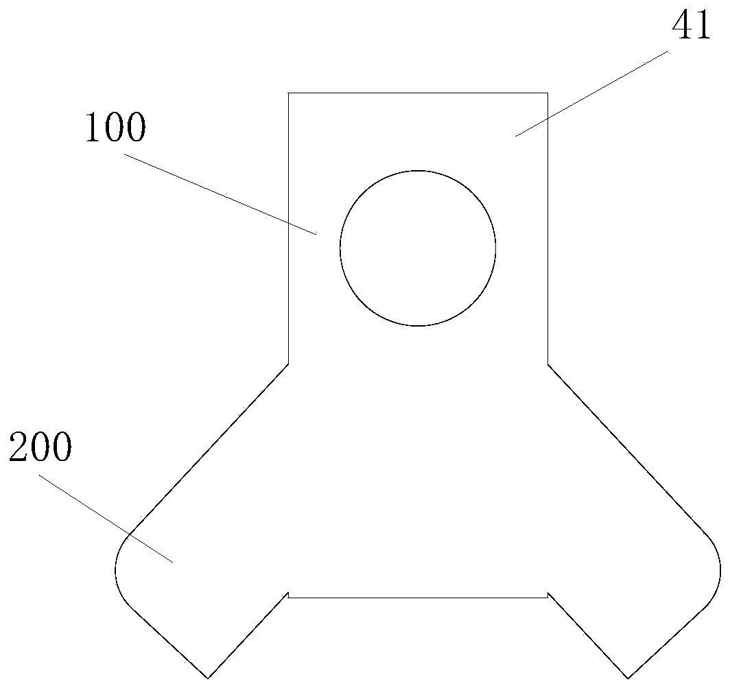
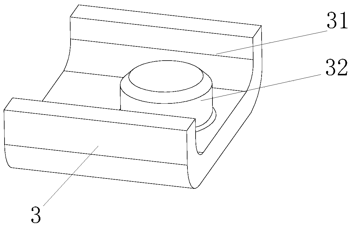
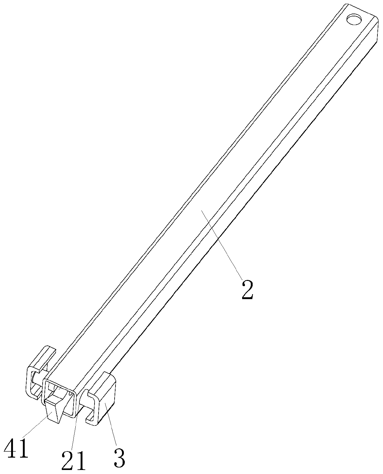
[0035] Figure 1 to Figure 6 The first preferred embodiment of the self-locking pull rod of the present invention is shown, which includes an outer tube 1 and an inner tube 2 sleeved in the outer tube 1, the outer tube 1 is fixed, the inner tube 2 is pulled up and down, and the side of the outer tube 1 There are several locking holes 11 for locking the outer tube, for the convenience of explanation, in this embodiment, the locking holes 11 for locking the locking of the outer tube are set on the right side of the outer tube 1 as an example. The bottom of the inner tube 2 is fixed with a stop buckle 41. The lower part of the stop buckle 41 is heavier than the upper part. The stop buckle 41 includes a fixed part 100 on the upper part and a protrusion on the same side as the lock hole 11 of the outer tube stop buckle at the lower part. Part 200, the fixing part 100 is provided with a through hole, and the stop buckle 41 is installed on the bottom of the inner tube 2 through the f...


PUM


Abstract

The invention relates to a self-locking drawbar and a draw-bar box. The self-locking drawbar comprises an outer pipe and an inner pipe, wherein the outer pipe sleeves the inner pipe, a plurality of outer pipe stop and receive buckle keyholes are formed in the side surface of the outer pipe, a stop and receive buckle is fixed to the bottom of the inner pipe, when the drawbar is inclined, the stop and receive buckle is inclined by gravity, bottom protrusions slide into the outer pipe stop and receive buckle keyholes to clamp the inner pipe, and thus the inner pipe cannot go down; when the innerpipe is pulled upwards, the stop and receive buckle slides out of the outer pipe stop and receive buckle keyholes by the downward force of the side wall of the outer pipe, and the inner pipe is pulledupwards freely. Self-locking of the drawbar is accomplished through matching of the stop and receive buckle with the outer pipe and the inner pipe, manifold components and parts of a traditional drawbar such as a button, a spring, a sliding block, a pressing rod and a pressing foot are not needed, the structure is simple, the weight of the drawbar is reduced, the manufacturing cost is reduced, the production process is simplified, the overall design sense of the drawbar is enhanced, and the self-locking drawbar is convenient for users to use.

Description

technical field [0001] The invention relates to the technical field of pull rods, more specifically, to a self-locking pull rod and a pull rod case. Background technique [0002] At present, the pull rod mechanism of the trolley box is a combination of inner and outer tubes. The button on the top controls the slider at the lower part, and the spring is used to pop the slider out of the hole on the tube wall to block the outer tube. Then press the button, the slider shrinks, and the outer tube The tube can be drawn and slid freely, and the whole tie rod structure has many parts, and the structure and production process are complicated. Contents of the invention [0003] The technical problem to be solved by the present invention is to provide a self-locking trolley and trolley case, which has a simple structure and does not require many parts such as buttons, springs, and sliders of the traditional trolley, thereby reducing manufacturing costs and simplifying the production...

Claims


Application Information

Patent Timeline
Patent Type & Authority Applications(China)
IPC IPC(8): A45C13/26
CPCA45C13/262
Inventor 曾冰
Owner 曾冰
Why Eureka
Try Eureka