
A glass clamping mechanism of a fully automatic backlight assembly machine

A technology for installing mechanical glass and clamping mechanism, which is applied to work accessories, manufacturing tools, stone processing tools, etc., can solve the problems of inability to put down the glass, inconvenient processing, and inconvenient operation, and achieves improved production and processing efficiency and reasonable structural design. Effect

Active Publication Date: 2020-11-03
安徽钦同瓶业有限公司
View PDF1 Cites 0 Cited by
  • Summary
  • Abstract
  • Description
  • Claims
  • Application Information

AI Technical Summary

Problems solved by technology

However, the glass clamping mechanism of this fully automatic backlight assembly machine still has shortcomings. First, the alignment of each group of clamping blocks needs to be considered during the clamping operation process, which takes a long time and is not convenient enough to operate; The magnetic or snapping effect between the clamping blocks is realized, and the glass cannot be put down quickly and automatically when moving to the designated position, which is not convenient for subsequent processing

Method used


Image

  • A glass clamping mechanism of a fully automatic backlight assembly machine
  • A glass clamping mechanism of a fully automatic backlight assembly machine
  • A glass clamping mechanism of a fully automatic backlight assembly machine

Examples


Embodiment Construction

[0021] The following will clearly and completely describe the technical solutions in the embodiments of the present invention with reference to the accompanying drawings in the embodiments of the present invention. Obviously, the described embodiments are only some, not all, embodiments of the present invention. Based on the embodiments of the present invention, all other embodiments obtained by persons of ordinary skill in the art without creative efforts fall within the protection scope of the present invention.

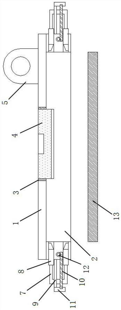
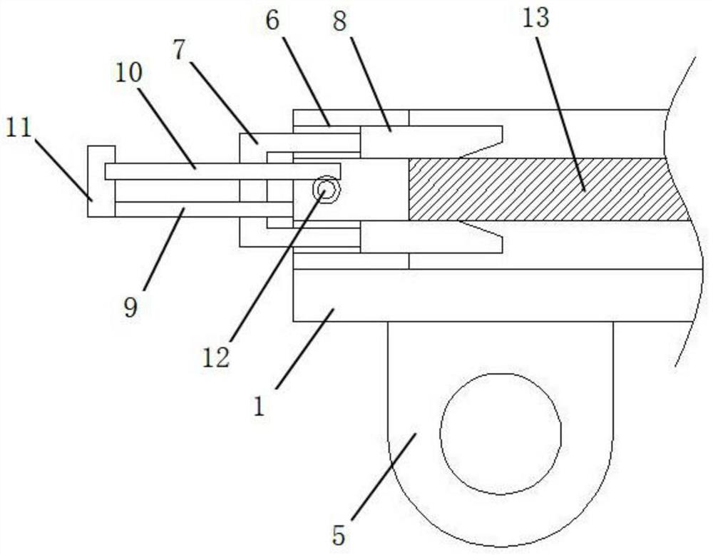
[0022] see Figure 1-3 As shown, this embodiment is a glass clamping mechanism of a fully automatic backlight assembly machine, including a bearing seat 1. The upper end of the bearing seat 1 is inwardly provided with a rectangular groove 2 matching the glass 13 specifications, and the bearing seat 1 is located in the rectangular groove 1. The bottom wall of the bottom wall is provided with a threaded hole 3, and the height adjustment support block 4 is screwed in ...


PUM


Abstract

The invention discloses a full-automatic backlight assembly machine glass clamping mechanism. The mechanism comprises a bearing base. A rectangular groove is formed inwards in the upper end of the bearing base. A height-adjusting supporting block is in screw joint with the bottom wall of the rectangular groove. A connecting base is fixed to the bottom end of the bearing base. Double sliding grooves are formed in the two side walls of the rectangular groove correspondingly. Two clamping strips are in sliding connection with each of the interiors of the double sliding grooves correspondingly andare fixed to the two ends of a U-shaped push plate correspondingly. A guide rod and an adjusting rod penetrate through a web portion of each U-shaped push plate. Two driving rods symmetrically penetrate through the bearing base. The driving rods and the two adjusting rods on the corresponding sides form umbrella-shaped steering mechanisms correspondingly. The outer ends of the driving rods are fixedly connected with output shafts of driving motors correspondingly. The mechanism is reasonable in structural design, the placed-in glass is effectively clamped by means of an automatic clamping andplacing mechanism, a manipulator overturns in a cooperative mode when the glass is moved to a designated position, the glass is stably placed down, the glass is effectively clamped, and the production and processing efficiency is improved.

Description

technical field [0001] The invention relates to the technical field of a fully automatic backlight assembly machine, in particular to a glass clamping mechanism of a fully automatic backlight assembly machine. Background technique [0002] The backlight automatic assembly machine is to automatically assemble the small backlight module on the fixture tray according to the production process requirements. The assembly sequence is: manually place the outer frame of the backlight module on the turntable mould→clean automatically (dust removal, static electricity removal)→(attach the diffuser sheet)→attach the first enhancement sheet→attach the second enhancement sheet→attach the shading sheet→pressing, Automatically take out the finished product and pick it up to the conveyor belt. With the development of society, the installation method of automatic backlight assembly machine is more and more widely used, and the use of automatic backlight assembly machine is increasing. The ...

Claims


Application Information

Patent Timeline
Patent Type & Authority Patents(China)
IPC IPC(8): B28D1/14B28D7/00B28D7/04
CPCB28D1/14B28D7/00B28D7/04
Inventor 王健赛少青
Owner 安徽钦同瓶业有限公司
Learn More