Communication method of onshore remote control submerged buoy

A communication method and remote control technology, applied in the direction of electrical components, transmission systems, free space transmission, etc., can solve problems such as submerged mark damage, short action distance, and submersible mark system damage, and achieve flexible deployment, simple requirements, and convenient use Effect

Inactive Publication Date: 2019-08-30
NORTHWESTERN POLYTECHNICAL UNIV
View PDF8 Cites 3 Cited by
  • Summary
  • Abstract
  • Description
  • Claims
  • Application Information

AI Technical Summary

Problems solved by technology

The disadvantages are: the lack of early warning for the impact of environmental changes and surrounding targets, the corresponding response cannot be made in advance, and the depth adjustment of the submerged mark cannot be directly controlled manually; at the same time, because the system still uses the traditional acoustic release device, the operating distance is relatively short , when releasing the submersible, it is still necessary to recover the ship close to the release. Due to the effect of the current, there is a large uncertainty in the location of the submersible recovery, which is likely to cause the released submersible to be destroyed by a ship recovered nearby.
[0007] The above analysis shows that the various existing technologies and methods for adjusting the position of the submersible or releasing the submersible either rely on their own control system to adjust the position, or they have a short working distance and need to approach the submersible system for operation. If it is not timely, it will cause damage to the submersible system, and it will easily pose a certain threat to the submersible during the recovery process.

Method used


Image

  • Communication method of onshore remote control submerged buoy
  • Communication method of onshore remote control submerged buoy
  • Communication method of onshore remote control submerged buoy

Examples


Embodiment Construction

[0022] Now in conjunction with embodiment, accompanying drawing, the present invention will be further described:
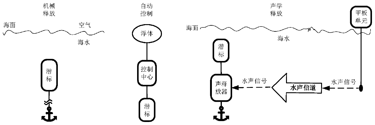
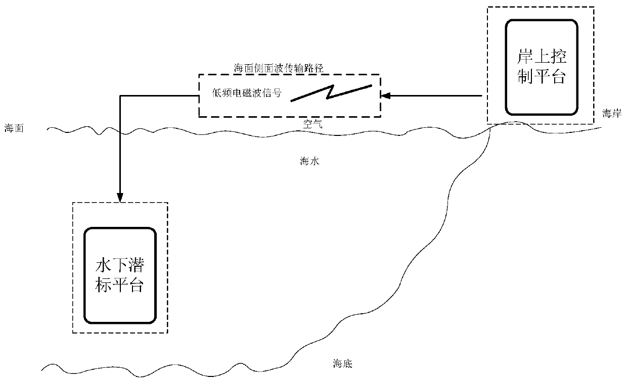
[0023] The idea of ​​the present invention is to use the very low frequency electromagnetic wave with strong seawater penetrating ability as the carrier of the control signal to realize the remote control of the submersible marking system on the shore, so as to make up for the traditional underwater acoustic / mechanical release device and automatic control of the submersible calibration depth. A series of disadvantages brought about by other methods at work. in figure 1 Presents three existing ways of controlling / releasing the submersible.

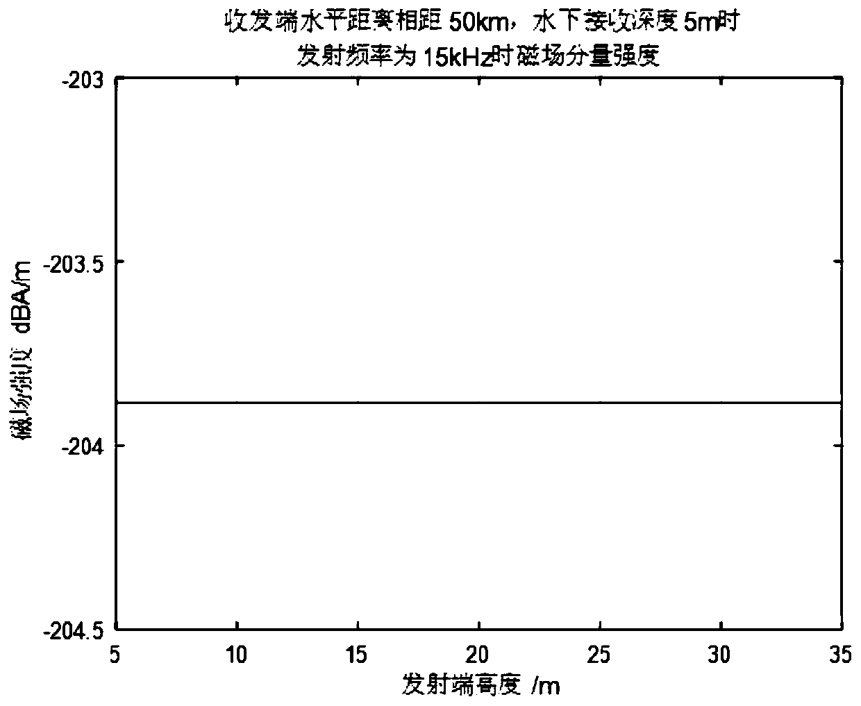
[0024] Embodiment of the present invention: the height of the transmitting antenna of the shore control terminal is 10m, the horizontal distance of sending and receiving is 20km, and the receiving depth of the submarine mark control system is 5m. The frequency of the electromagnetic wave signal transmitted in the control com...


PUM


Abstract

The invention relates to a communication method of an onshore remote control submerged buoy, which comprises the following steps: placing a control transmitting end on a coast, transmitting a very lowfrequency electromagnetic wave signal by using a transmitting antenna of a vertical dipole type by using the transmitting end, and realizing long-distance cross-interface propagation of control databy side waves of the surface layer of the sea water-air interface, wherein the submerged buoy receiving end is located in seawater, a vertical electric dipole antenna with the omnidirectional horizontal direction is used as a receiving antenna, and the situation that after the submerged buoy array is disturbed by ocean current, the transmitting end is located in the restrained direction possibly occurs to the horizontal dipole antenna is effectively avoided. Therefore, the smoothness of the communication control link is ensured. The receiving end antenna uses the vertical electric dipole antenna, so that the cable space of the submerged buoy is fully utilized, the increase of the propagation path of electromagnetic waves in seawater due to the fact that the receiving antenna is distributedtoo deep along with the release device is avoided, the electromagnetic field intensity at the receiving antenna is ensured, and the reliability of a control link is ensured.

Description

technical field [0001] The invention belongs to the technical fields of marine engineering, marine environment monitoring, and underwater radio communication, and relates to a communication method for remotely controlling a submersible buoy on the shore, which utilizes the characteristics of small attenuation of very low frequency electromagnetic waves and the direct transmission of electromagnetic waves across the ocean interface to realize communication with and on the shore. Remote control for deploying submersible buoys in the ocean. Background technique [0002] Submersible buoys are an important survey tool for observing and obtaining long-term marine scientific data, and are also an important part of the ocean observation network. They provide an important guarantee for marine environmental security such as national ocean forecasting, climate forecasting, disaster prevention and mitigation, and national defense security. With the establishment of a large-scale nationa...

Claims


Application Information

Patent Timeline
IPC IPC(8): H04B10/11H04B13/02
CPCH04B10/11H04B13/02
Inventor 王宏磊杨坤德任英达
Owner NORTHWESTERN POLYTECHNICAL UNIV
Why Eureka
Try Eureka