Middle-positioned quick-discharging hot water device and temperature control method

A hot water device and a mid-mounted technology, which are applied in the field of a mid-mounted quick-discharge hot water device and temperature control, can solve problems such as unfavorable environmental protection, unintelligence, and large power consumption, so as to improve the degree of intelligence and environmental protection, and improve the use experience. , the effect of reducing power consumption

Active Publication Date: 2019-08-30
张领
View PDF10 Cites 0 Cited by
  • Summary
  • Abstract
  • Description
  • Claims
  • Application Information

AI Technical Summary

Problems solved by technology

[0002] At present, gas or electric water heaters are widely used in the market. However, due to the terminal heating method of gas or electric water heaters, the heated hot water is transported to the water supply through the water distribution pipe. The distance between the pipelines is long and the accumulated cold water is large. As a result, it takes a long time to drain the cold water to use hot water, and it will also cause a waste of water resources; in order to solve this problem, there are also quick hot water faucets on the market, which heat the cold water flowing through the faucet by adding a heating device to the faucet. However, this kind of fast hot water faucet works through water flow control. After it is turned on, it will continue to heat the water flow and continue to consume electricity. In case of cold water discharge

Method used


Image

  • Middle-positioned quick-discharging hot water device and temperature control method
  • Middle-positioned quick-discharging hot water device and temperature control method
  • Middle-positioned quick-discharging hot water device and temperature control method

Examples


Embodiment

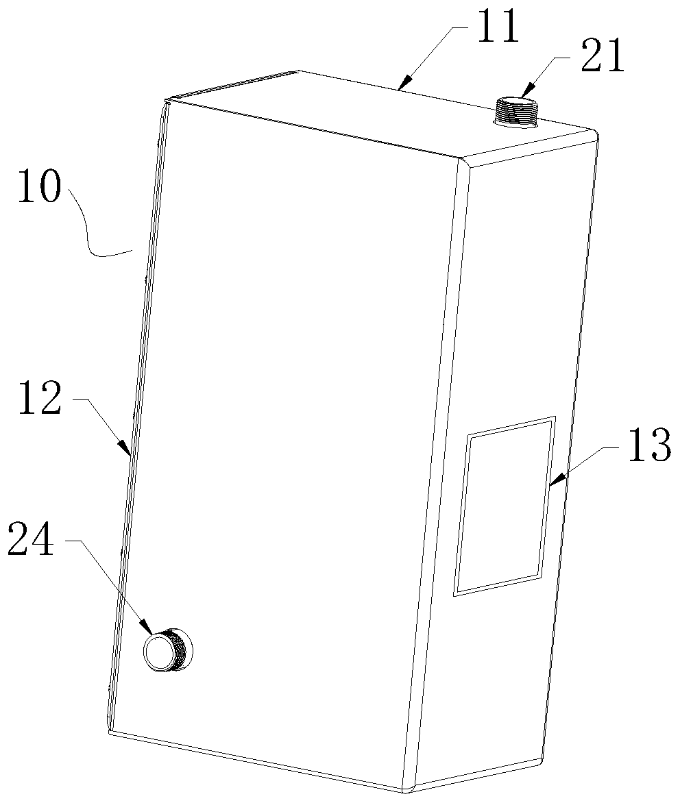
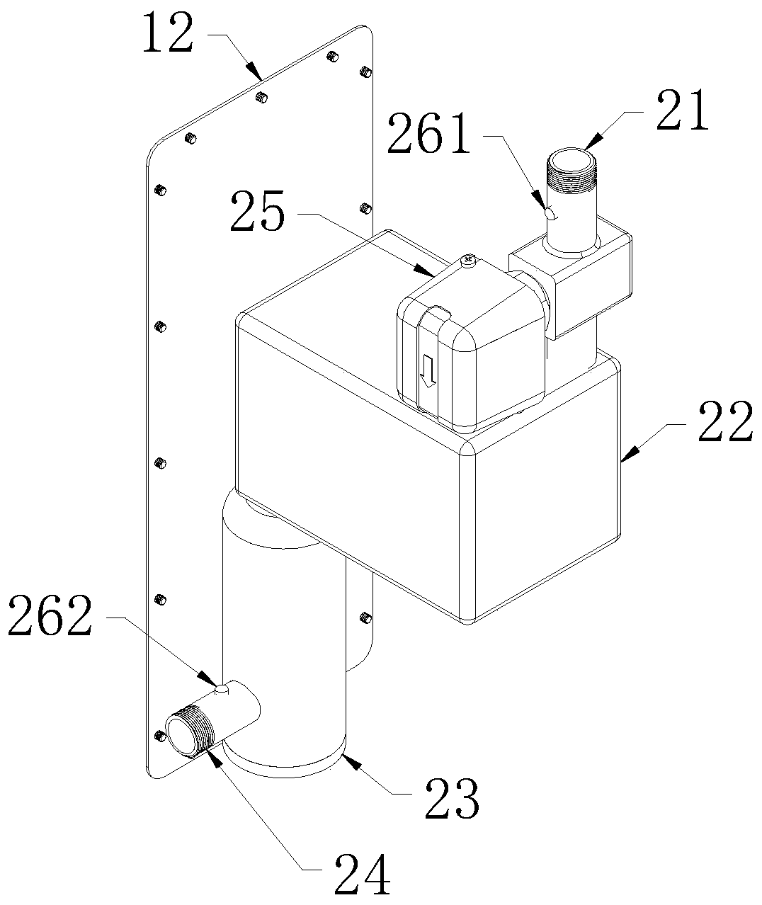
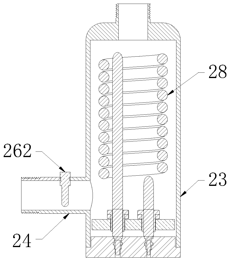
[0033] Such as Figure 1~3 As shown, the middle-mounted quick hot water device includes a quick hot water device body 10 installed between the gas water heater and the faucet. The quick hot water device body 10 communicates with the hot water pipeline of the faucet. The hot water outlet device body 10 includes a housing 11 with an opening at one end and a back plate 12 installed at the opening end of the housing 11. A water inlet pipe 21, a heating water pipe 23 and a water outlet pipe 24 connected in sequence are installed in the housing 11. A heating pipe 28 is installed in the heating water pipe 23, and a first thermocouple 261 and a flow switch 25 are installed on the pipe body of the water inlet pipe 21, and the flow switch 25 is a target type or a pressure type or an electronic type. The first thermocouple 261 is electrically connected with a first temperature control switch (not shown in the figure), and the first temperature control switch is electrically connected wit...


PUM


Abstract

The invention discloses a middle-positioned quick-discharging hot water device and a temperature control method. The quick-discharging hot water device comprises a quick-discharging hot water device body; the quick-discharging hot water device body comprises a shell and a back plate; a water inlet pipe, a heating water pipe and a water outlet pipe which communicate with one another sequentially are arranged in the shell; a heating pipe is arranged in the heating water pipe; a first thermocouple and a flow switch are arranged on a pipe body of the water inlet pipe; the first thermocouple is electrically connected with a first temperature control switch; the first temperature control switch is electrically connected with the heating pipe; a second thermocouple is arranged on a pipe body of the water outlet pipe; the second thermocouple is electrically connected with a second temperature control switch; and the second temperature control switch is electrically connected with the heating pipe. The temperature control method comprises four steps of S1, heating cold water; S2, detecting water temperature; S3, verifying target temperature; and S4, correcting temperature. The cold water inthe water pipe can be heated intelligently and timely; waste of water resources caused by the fact that the pipeline is too long is avoided; electricity consumption is reduced; and the intelligence degree and the environmental friendliness are improved.

Description

technical field [0001] The invention belongs to the technical field of heaters, and in particular relates to a center-mounted quick-out hot water device and a temperature control method. Background technique [0002] At present, gas or electric water heaters are widely used in the market. However, due to the terminal heating method of gas or electric water heaters, the heated hot water is transported to the water supply through the water distribution pipe. The distance between the pipelines is long and the accumulated cold water is large. As a result, it takes a long time to drain the cold water to use hot water, and it will also cause a waste of water resources; in order to solve this problem, there are also quick hot water faucets on the market, which heat the cold water flowing through the faucet by adding a heating device to the faucet. However, this kind of fast hot water faucet works through water flow control. After it is turned on, it will continue to heat the water ...

Claims


Application Information

Patent Timeline
IPC IPC(8): F24H9/20
CPCF24H9/2035
Inventor 张领
Owner 张领
Why Eureka
Try Eureka