
Electrical control clutch booster

A technology for clutches and boosters, which is applied to clutches, mechanical equipment, etc., can solve problems such as the inability of the controller to automatically control the intake and exhaust of the booster, and achieve high shift comfort and smoothness, fast work response, and high precision Effect

Inactive Publication Date: 2019-08-30
ZHEJIANG KELI VEHICLE CONTROL SYST
View PDF1 Cites 5 Cited by
  • Summary
  • Abstract
  • Description
  • Claims
  • Application Information

AI Technical Summary

Problems solved by technology

[0006] The present invention provides an electronically controlled clutch booster aiming at the shortcomings in the prior art that the controller cannot automatically control the intake and exhaust of the booster

Method used


Image

  • Electrical control clutch booster
  • Electrical control clutch booster
  • Electrical control clutch booster

Examples


Embodiment 1

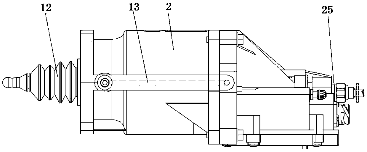
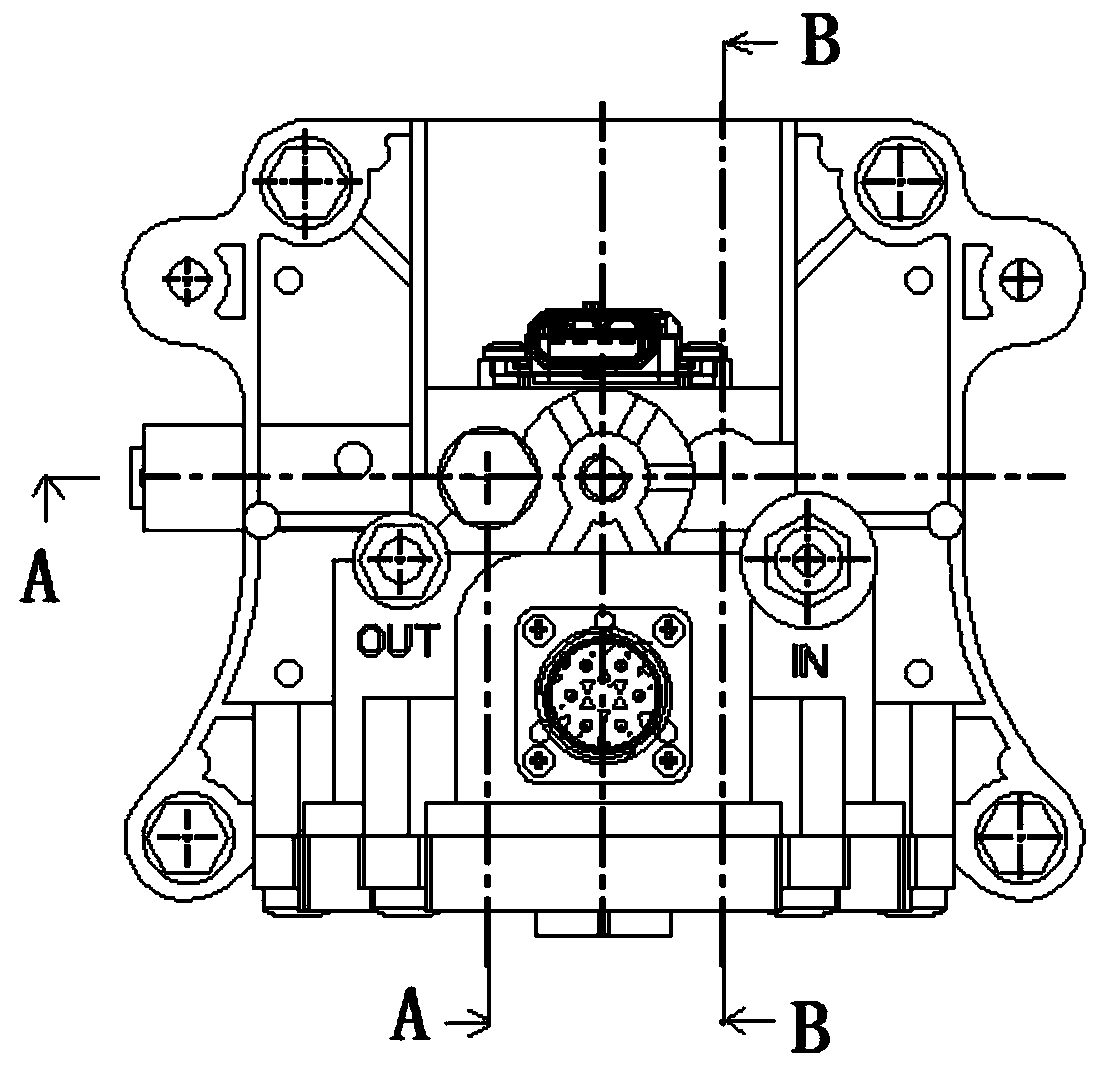
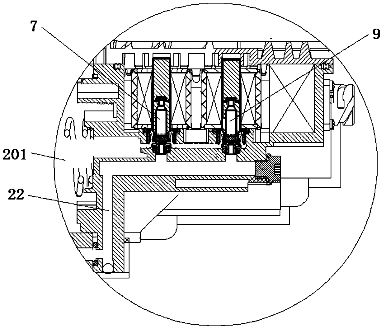
[0028] The electronically controlled clutch booster, as shown in the figure, includes a cylinder body 2. A piston 1 is installed inside the cylinder body 2 to separate the inner cavity of the cylinder body 2. The piston 1 divides the cylinder body 2 into a chamber A 201 and a chamber B 202. The piston 1 1 is installed with a magnet 3, and also includes a controller 5. A Hall sensor 10 is installed on the cylinder 2. The Hall sensor 10 senses the movement of the magnet 3 in the cylinder 2 and forms a position signal to the controller 5. The position signal It is sent in the form of PWM value, and also includes the first solenoid valve 6 and the second solenoid valve 7, the first solenoid valve 6 and the second solenoid valve 7 respectively control the intake of the A chamber 201 and the B chamber 202, and the controller 5 controls the A solenoid valve 6 and a second solenoid valve 7 work. The controller 5 is a TCU controller.

[0029] Also includes a third solenoid valve 8 and...

Embodiment 2

[0045] The same as Embodiment 1, the difference is that it also includes a return spring 4, which is installed between the annular end cover 20022 and the front piston 1001 and pushes the piston 1 to move left. The return spring 4 can ensure that the piston 2 is pushed to the initial position to ensure the space of the A cavity 201 .

Embodiment 3

[0047] Same as Embodiment 1, the difference is that the front cylinder body 2001 is a cylindrical body with openings at the left and right ends, and the left end opening of the front cylinder body 2001 is sealed with a telescopic dust cover 12, and the rear cylinder body 2002 includes a small-diameter cylinder body 20021 and an annular The end cap 20022, the left end opening of the small-diameter barrel 20021, the annular end cap 20022 is located at the edge of the opening of the small-diameter sleeve 20021, the end cap 20022 is sealed and installed at the right end opening of the front cylinder body 2001, the right section of the rear piston 1002 is in contact with the small-diameter barrel The inner wall of the body 20021 forms a cavity C 203 , and the cavity C 203 communicates with the cavity A 201 . A small hole 2031 is provided on the wall near the right end of the cavity C 203 , and a channel is also included. The small hole 2031 communicates with the channel, and the cha...


PUM


Abstract

The invention relates to the field of clutch boosters, and discloses an electrical control clutch booster. The electrical control clutch booster comprises a cylinder body (2), a controller (5), a first electromagnetic valve (6) and a second electromagnetic valve (7) , wherein a piston (1) separating an inner cavity of the cylinder body (2) is arranged in the cylinder body (2); a magnet (3) is arranged on the piston (1); a Hall sensor (10) is arranged on the cylinder body (2); the Hall sensor (10) is able to sense the movement of the magnet (3) in the cylinder body (2) and forms a position signal to be sent to the controller (5); and the controller (5) controls the first electromagnetic valve (6) and the second electromagnetic valve (7) to work. According to the electrical control clutch booster, the position of the piston in the cylinder body can be accurately monitored by the Hall sensor in real time, the normally-closed high-frequency electromagnetic valves are controlled by the TCUcontroller to be powered on or off, and therefore the clutch can be disengaged and engaged, and has quick working response, high accuracy, high comfort and smoothness in shifting, and no pollution.

Description

technical field [0001] The invention relates to the field of clutch boosters, in particular to an electronically controlled clutch booster. Background technique [0002] In order to facilitate the driver to manipulate and shift gears, there is a clutch pedal mechanism in the cab. When the pedal is stepped on, the clutch master cylinder and clutch booster are driven to perform pneumatic boosting, so that the clutch is separated, and then the driver can manually shift gears to raise or lower the vehicle. driving speed. [0003] At present, the clutch booster of commercial vehicles mainly works together through the two media of brake fluid and compressed air: by stepping on the clutch pedal, the brake fluid in the clutch master cylinder is pushed into the clutch booster, so that the brake fluid generates hydraulic pressure, and then The hydraulic pressure will open the valve of the clutch booster, and the compressed air will enter the clutch booster through the valve to assist...

Claims


Application Information

Patent Timeline
Patent Type & Authority Applications(China)
IPC IPC(8): F16D48/04F16D48/06
CPCF16D48/04F16D48/066F16D2048/0212F16D2048/0221F16D2048/0266
Inventor 何徐耿孔涛
Owner ZHEJIANG KELI VEHICLE CONTROL SYST
Learn More