


Quick Research
Generate reliable direction feasibility study reports for your R&D in just a few steps.

Technical Q&A
Discover and master advanced knowledge NOW. Basics, ideas, possibilities, all at once.

Find Solutions
As an expert in R&D theories, this can generate solutions to your technical problems instantly.

Evaluate Feasibility
Analyze your overall solution with one click, know your potential R&D risks in advance.

Monitor Landscape
Get weekly tech updates, stay abreast of the latest tech innovations and key insights.
Air visibility monitoring system and method based on camera
A monitoring system and camera technology, applied in closed-circuit television systems, scattering characteristic measurement, instruments, etc., can solve the problems of decreased detection accuracy, difficulty in dense layout, limited sample space, etc., and achieve the effect of simple operation, comprehensive monitoring, and simple steps
- Summary
- Abstract
- Description
- Claims
- Application Information
AI Technical Summary
Problems solved by technology
Method used
Image

Examples
Embodiment 1
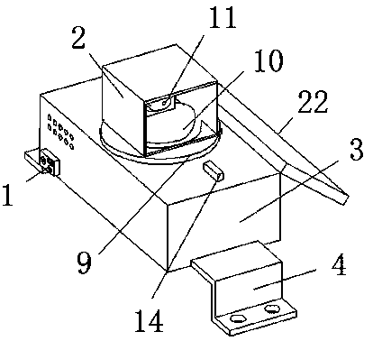
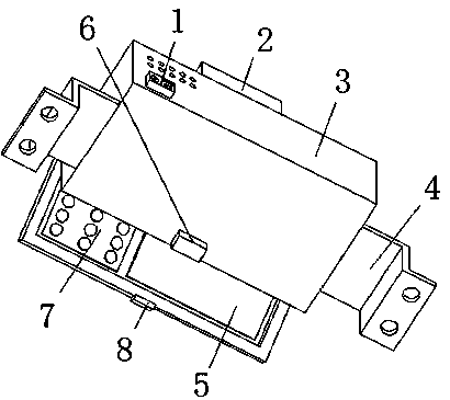
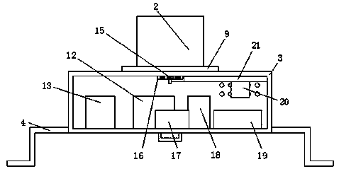
[0024] A camera-based monitoring system for air visibility, comprising a lower connection box 3, the upper surface of the lower connection box 3 is connected with an upper rotating disk 9 through a short shaft, and the lower end of the short shaft penetrates and extends to the inside of the lower connection box 3, and The lower end of the short shaft is connected with a gear 15 by bolts, and the upper inner side of the lower end connection box 3 is connected with an electric telescopic rod 21 by bolts, and the telescopic end of the electric telescopic rod 21 is connected with a connecting rack 16 by bolts, and the connecting rack 16 and The gears 15 are meshed with each other, the upper surface of the upper rotating disc 9 is provided with a camera connection seat 10, the upper surface of the camera connection seat 10 is provided with a camera 11, the upper surface side of the lower connection box 3 is provided with an air quality detector 14, and the lower end is connected to ...
Embodiment 2
[0026] A camera-based monitoring system for air visibility, comprising a lower connection box 3, the upper surface of the lower connection box 3 is connected with an upper rotating disk 9 through a short shaft, and the lower end of the short shaft penetrates and extends to the inside of the lower connection box 3, and The lower end of the short shaft is connected with a gear 15 by bolts, and the upper inner side of the lower end connection box 3 is connected with an electric telescopic rod 21 by bolts, and the telescopic end of the electric telescopic rod 21 is connected with a connecting rack 16 by bolts, and the connecting rack 16 and The gears 15 are meshed with each other, the upper surface of the upper rotating disc 9 is provided with a camera connection seat 10, the upper surface of the camera connection seat 10 is provided with a camera 11, the upper surface side of the lower connection box 3 is provided with an air quality detector 14, and the lower end is connected to ...
Embodiment 3
[0028]A camera-based monitoring system for air visibility, comprising a lower connection box 3, the upper surface of the lower connection box 3 is connected with an upper rotating disk 9 through a short shaft, and the lower end of the short shaft penetrates and extends to the inside of the lower connection box 3, and The lower end of the short shaft is connected with a gear 15 by bolts, and the upper inner side of the lower end connection box 3 is connected with an electric telescopic rod 21 by bolts, and the telescopic end of the electric telescopic rod 21 is connected with a connecting rack 16 by bolts, and the connecting rack 16 and The gears 15 are meshed with each other, the upper surface of the upper rotating disc 9 is provided with a camera connection seat 10, the upper surface of the camera connection seat 10 is provided with a camera 11, the upper surface side of the lower connection box 3 is provided with an air quality detector 14, and the lower end is connected to T...
PUM
 Abstract
Description
Claims
Application Information
 - R&D Engineer
- R&D Manager
- IP Professional
- Industry Leading Data Capabilities
- Powerful AI technology
- Patent DNA Extraction
Browse by: Latest US Patents, China's latest patents, Technical Efficacy Thesaurus, Application Domain, Technology Topic, Popular Technical Reports.
© 2024 PatSnap. All rights reserved.Legal|Privacy policy|Modern Slavery Act Transparency Statement|Sitemap|About US| Contact US: help@patsnap.com