
Automatic overturning, welding and dispensing machine and automatic overturning, welding and dispensing process

An automatic flipping and welding point technology, applied in welding equipment, auxiliary welding equipment, welding/cutting auxiliary equipment, etc., can solve problems such as poor effect, low efficiency, and inconformity with mass production

Pending Publication Date: 2019-08-27
DONGGUAN SANXIN PRECISION MACHINERY
View PDF0 Cites 2 Cited by
  • Summary
  • Abstract
  • Description
  • Claims
  • Application Information

AI Technical Summary

Problems solved by technology

[0002] In the early days, operations such as welding and dispensing of wire rods were mainly done manually, which was low in efficiency, poor in effect, high in labor intensity and high in labor costs, and did not meet the requirements of mass production.
Later, automatic welding machines, automatic dispensing machines, etc. appeared. However, for the assembly line, there are still many manual operations between the connecting stations. For example, when double-sided welding is required, usually use One side is welded first, and then the operator turns the workpiece over, and then welds the other side. Similarly, when double-sided dispensing is required, one side is first dispensed, and then the operator turns the workpiece over, and then dispenses Another aspect; in this way, the processing efficiency of the entire assembly line is limited, and at the same time, it is easy to cause uncontrollable processing quality due to human factors

Method used


Image

  • Automatic overturning, welding and dispensing machine and automatic overturning, welding and dispensing process
  • Automatic overturning, welding and dispensing machine and automatic overturning, welding and dispensing process
  • Automatic overturning, welding and dispensing machine and automatic overturning, welding and dispensing process

Examples


Embodiment Construction

[0038] Please refer to Figure 1 to Figure 7 As shown, it shows the specific structure of the embodiment of the present invention.

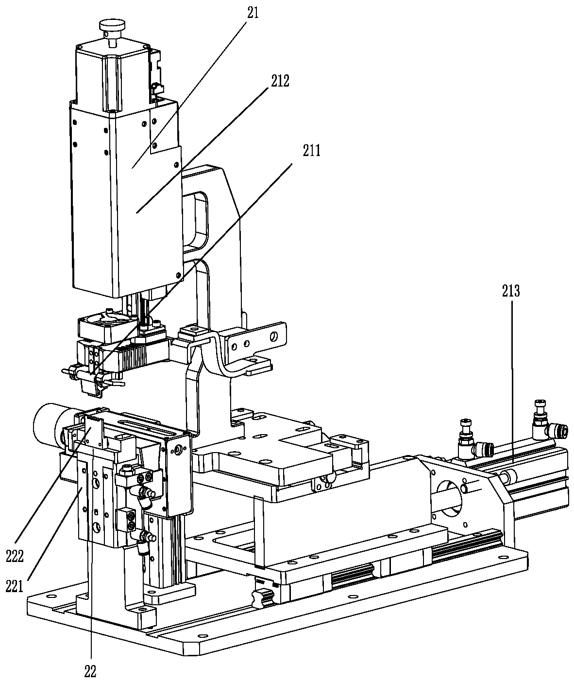
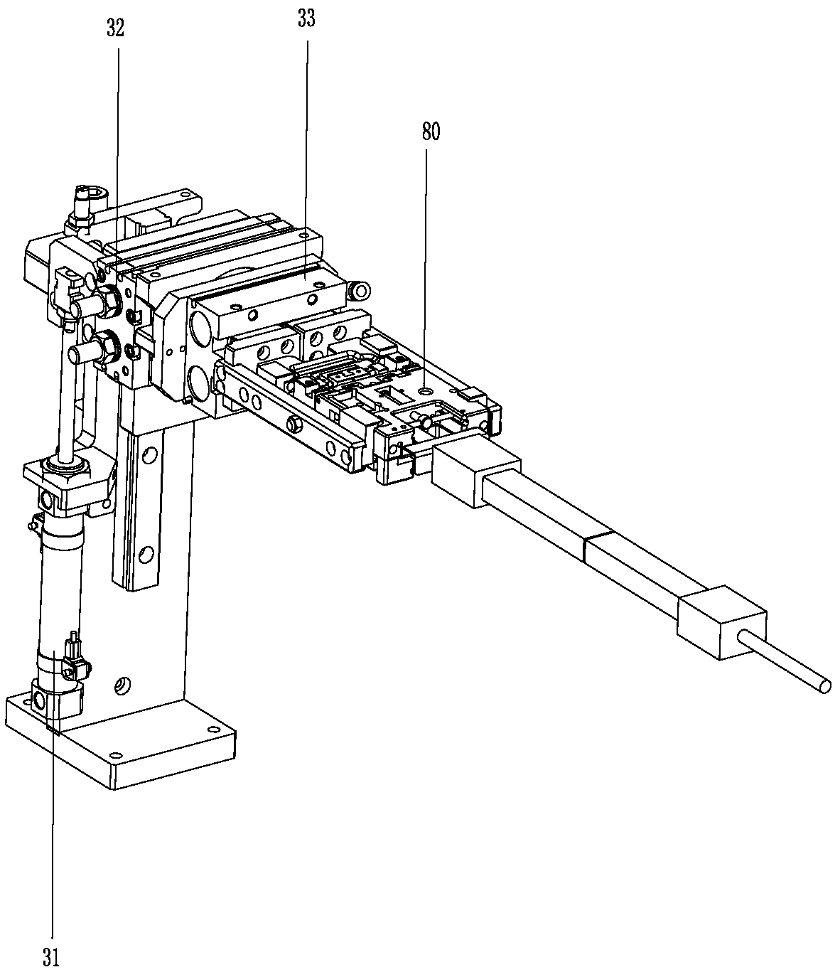
[0039] Such as figure 1 As shown, an automatic flip welding and dispensing all-in-one machine includes a frame 10, the frame 10 is provided with a fixture conveying flow channel, and a front welding station, a first treatment station, and a first welding station are sequentially arranged along the extending direction of the fixture conveying flow path. Tool turning station, reverse welding station, glue dispensing station and double-sided curing station; the workpiece is installed on the clamping jig 80, and the clamping jig 80 passes through all the stations in turn through the runner claw. Generally, the workpiece may refer to a PCB board or a connector that needs to be soldered on both sides. The front welding station is equipped with a front welding module 20, the first jig turning station is equipped with a first jig turning module 30, and...


PUM


Abstract

The invention discloses an automatic overturning, welding and dispensing machine and an automatic overturning, welding and dispensing process. In the processing process, a workpiece needing to be subjected to double-sided welding is firstly fixed on a wire clamping fixture, and the wire clamping fixture is placed in a clamp conveying runner and is sent to all stations through the clamp conveying runner; the front face of the workpiece is welded at the front face welding stations in sequence, the wire clamping fixture is overturned by 180 degrees at a first fixture overturning station to enablethe back face of the workpiece to be upward, the back face of the workpiece is welded from the front face at the back face welding stations, dispensing is carried out on the front face of the workpiece at the dispensing station, then the wire clamping fixture is overturned by 180 degrees to enable the back face of the workpiece to be upward, then dispensing is carried out on the back face of theworkpiece from the front face, in this way, dispensing of the front and back faces is completed at the same dispensing station, and curing is carried out on the front and back faces of the workpiece at a double-face curing station; and fully-automated operation is achieved, labor cost is reduced, and the processing efficiency and yield are improved.

Description

technical field [0001] The invention relates to the technology in the field of wire rod assembly, in particular to an automatic flip welding and dispensing integrated machine and an automatic flip welding and dispensing process. Background technique [0002] In the early days, operations such as welding and dispensing of wire rods were mainly done manually, which was low in efficiency, poor in effect, high in labor intensity and high in labor costs, and did not meet the requirements of mass production. Later, automatic welding machines, automatic dispensing machines, etc. appeared. However, for the assembly line, there are still many manual operations between the connecting stations. For example, when double-sided welding is required, usually use One side is welded first, and then the operator turns the workpiece over, and then welds the other side. Similarly, when double-sided dispensing is required, one side is first dispensed, and then the operator turns the workpiece ove...

Claims


Application Information

Patent Timeline
IPC IPC(8): B23K37/00B23K37/047B05C5/02B05C9/12B05C13/02B05D3/06
CPCB23K37/00B23K37/047B05C5/0208B05C13/02B05C9/12B05D3/067
Inventor 姚天金
Owner DONGGUAN SANXIN PRECISION MACHINERY
Learn More