Microporous reaction kettle
A reaction kettle and microporous technology, applied in the field of chemical preparation equipment, can solve the problems of short residence time, lack of reaction raw materials, and unsuitable dispersants, etc., to avoid local reactions too fast, ensure production efficiency, and avoid mutual influence Effect
- Summary
- Abstract
- Description
- Claims
- Application Information
AI Technical Summary
Problems solved by technology
Method used
Image

Examples
Embodiment 1
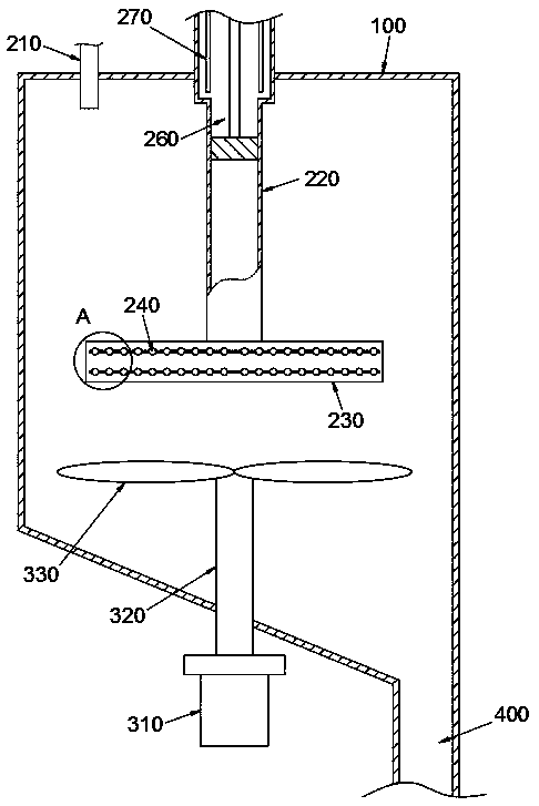
[0038] Example 1: Reference figure 1 A microporous reaction kettle shown includes a kettle body 100 , a feeding mechanism 200 , a stirring mechanism 300 , and a discharging mechanism 400 . Wherein, the stirring mechanism 300 adopts a lower driving type, that is, the stirring drive member 310 (such as a motor) is located below the kettle body 100; meanwhile, the kettle body 100 is based on any one of the kettle body structures in the prior art. The bottom of the body 100 is inclined; the discharge mechanism 400 is arranged on the bottom of the kettle body 100 on the basis of any discharge mechanism structure in the prior art (such as including a discharge pipeline, a buffer, a discharge pump, etc.) Tilt low to facilitate complete discharge.
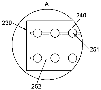
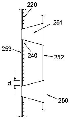
[0039]The feeding mechanism 200 includes a first feeding pipeline 210, a second feeding pipeline 220, a feeding unit 230, an opening and closing unit 250 for closing or opening the feeding micropore 240, and a piston unit 260 arranged in ...
Embodiment 2
[0054] Embodiment 2: the difference between embodiment 2 and embodiment 1 is that, refer to Figure 6 and Figure 7 As shown, the feeding unit 230 includes a plurality of sub-feeding chambers 232 arranged independently of each other. For example, in this embodiment, it includes 4 sub-feeding chambers 232 of the same shape, and the 4 sub-feeding chambers 232 can be assembled into a round cake shape. The feeding unit 230. Each sub-feeding chamber 232 is respectively fixed to the lower part of the second feeding pipe 220 by welding, and the upper surface of the part located in the space of the second feeding pipe 220 is provided with openings.
[0055] The secondary feeding pipe 270 in this embodiment extends to communicate with the sub-feeding chamber 232 . Specifically, the number of secondary feeding pipes 270 is the same as that of the sub-feeding chambers 232, and they correspond one-to-one, and extend to the sub-feeding chambers 232 to communicate with the openings on the...
Embodiment 3
[0056] Embodiment 3: the difference between embodiment 3 and embodiment 1 is that, refer to Figure 8 and Figure 9 As shown, in this embodiment, the feeding unit 230 includes a main feeding chamber 231, a plurality of (for example, 4) sub-feeding chambers 232 communicated with the main feeding chamber 231 respectively, and the main feeding chamber 231 is round cake-shaped The upper surface of the hollow metal part can be relatively rotatably installed on the lower part of the second feeding pipe 220 through rolling bearings, and communicates with the second feeding pipe 220 . Its lower part has a concave platform, which is keyed to the stirring drive shaft 320 of the stirring mechanism 300 , so that the stirring drive shaft 320 can drive the main feeding chamber 231 . The sub-feeding chamber 232 is in the shape of a long rectangular hollow metal plate, one end of which is welded and fixed on the outer peripheral side wall of the main feeding chamber 231, and the sub-feeding ...
PUM
 Abstract
Description
Claims
Application Information
 - Generate Ideas
- Intellectual Property
- Life Sciences
- Materials
- Tech Scout
- Unparalleled Data Quality
- Higher Quality Content
- 60% Fewer Hallucinations
Browse by: Latest US Patents, China's latest patents, Technical Efficacy Thesaurus, Application Domain, Technology Topic, Popular Technical Reports.
© 2025 PatSnap. All rights reserved.Legal|Privacy policy|Modern Slavery Act Transparency Statement|Sitemap|About US| Contact US: help@patsnap.com