
Unmanned aerial vehicle pollination device

A technology of pollination device and unmanned aerial vehicle, which is applied in the direction of plant genetic improvement, botanical equipment and methods, applications, etc. It can solve the problems of inability to break the material body, the air velocity of the pollination outlet cannot be adjusted, and poor pollination stability. Achieve the effect of avoiding material agglomeration, facilitating scientific operation and ensuring uniformity

Pending Publication Date: 2019-08-27
珠海银通无人机科技有限公司
View PDF1 Cites 1 Cited by
  • Summary
  • Abstract
  • Description
  • Claims
  • Application Information

AI Technical Summary

Problems solved by technology

[0002] Auxiliary pollination is an operation with strong technical requirements, high precision requirements, and tight time requirements. In the prior art: the patent application publication number CN 109566408 A discloses a UAV pollination device, including the UAV body. The bottom of the machine body is hung with a pollen box, and the bottom of the pollen box is provided with a discharge port, and the discharge port is connected with at least one powder outlet pipe extending outwards, and any powder discharge pipe is provided with an air flow booster device to realize the discharge. The air pressure at the outlet end of the powder pipe is reduced so that the pollen in the pollen box is sucked out. It cannot break the material body, the uniformity of the material is poor, and it does not have the shock absorption ability. The mechanical vibration generated by the motor is likely to have a negative impact on the pollination operation. The airflow velocity of the powder outlet cannot be adjusted, and the pollination stability is poor

Method used


Image

  • Unmanned aerial vehicle pollination device
  • Unmanned aerial vehicle pollination device
  • Unmanned aerial vehicle pollination device

Examples


Embodiment Construction

[0030] The technical solutions in the embodiments of the present invention will be clearly and completely described below in conjunction with the accompanying drawings in the embodiments of the present invention. Obviously, the described embodiments are only a part of the embodiments of the present invention, rather than all the embodiments. Based on the embodiments of the present invention, all other embodiments obtained by those of ordinary skill in the art without creative work shall fall within the protection scope of the present invention.

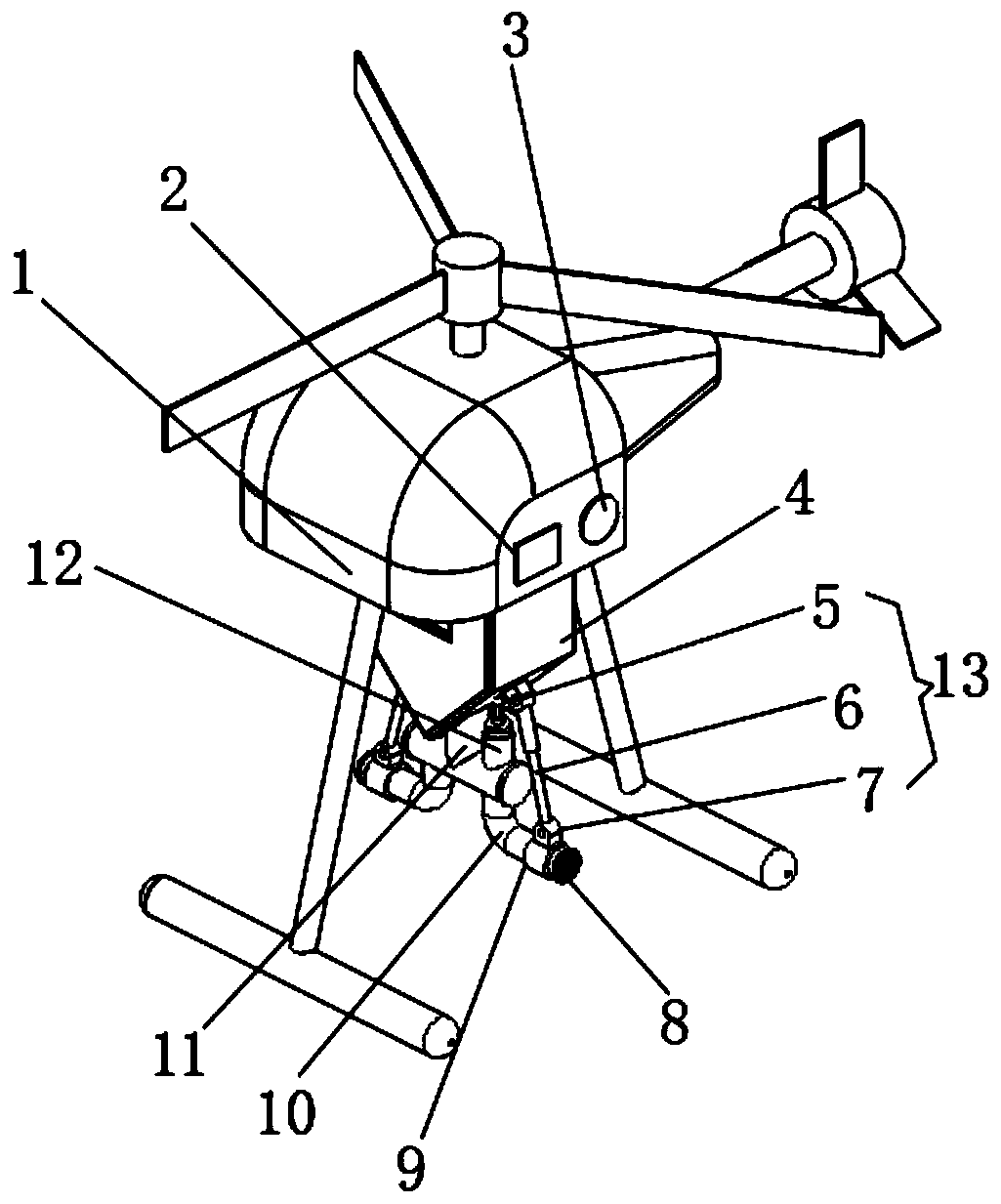
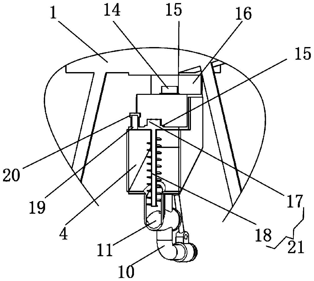
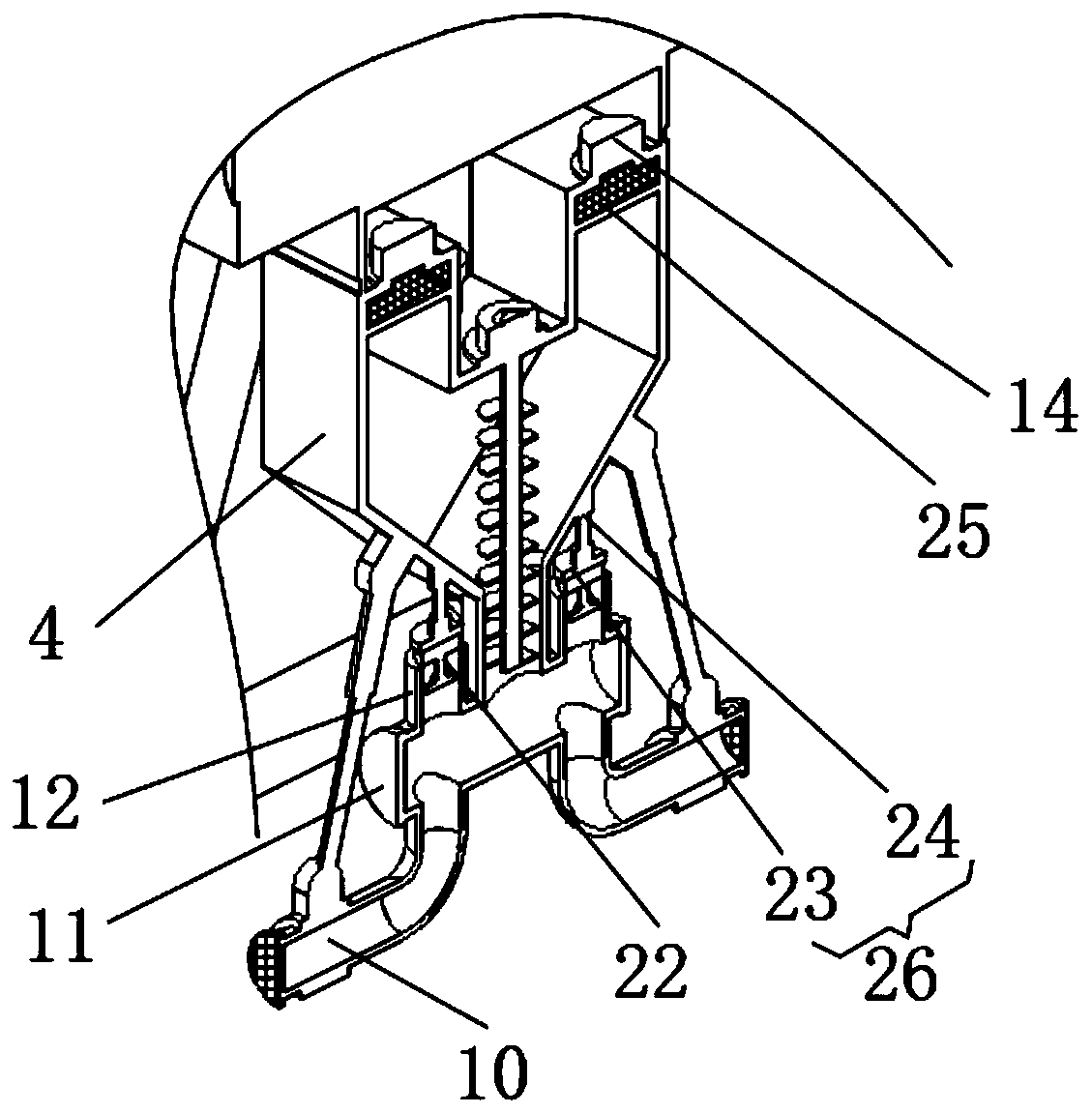
[0031] See Figure 1-3 , The present invention provides a technical solution: an unmanned aerial vehicle pollination device, including an unmanned aerial vehicle body 1, a pollination box 4, a booster fan 14, a feeding device 21, a duct 12, a elbow 10, and a shock absorption device 26 And adjustment mechanism 13;

[0032] Pollination box 4: The pollination box 4 is fixed on the bottom of the drone body 1;

[0033] Booster fan 14: The boost...


PUM


Abstract

The invention discloses an unmanned aerial vehicle pollination device comprising an unmanned aerial vehicle body, a pollination box, a booster fan, a feeding device, a culvert, a bend pipe, a shock absorber and a regulating mechanism. The pollination box is fixed onto the bottom of the unmanned aerial vehicle body; the booster fan is installed at the top of the pollination device, and the air outlet of the booster fan is communicated with the interior of the pollination box; the bend pipe is communicated with the culvert and the pollination box respectively through a feeding pipe, the positionnear the discharge outlet, on the bend pipe, is fixed with a fixing part, and a dust gauze is installed in the position of the discharge outlet of the bend pipe. The unmanned aerial vehicle pollination device has the advantages that a feeding motor drives spiral blades to rotate, the spiral blades breaks the material body and conveys the same to the feeding pipe, spiral feeding is specially usedfor the measurement and control of powdered materials to ensure quantitative feeding, which is convenient for scientific operation, and can break the materials, avoid caking of the materials and ensure the uniformity of discharge.

Description

Technical field [0001] The invention relates to the technical field of agricultural machinery equipment, in particular to an unmanned aerial vehicle pollination device. Background technique [0002] Auxiliary pollination is an operation with strong technical requirements, high precision requirements, and tight time requirements. In the prior art: the patent application publication number CN 109566408 A discloses a drone pollination device, including the drone body, unmanned The bottom of the machine body is hung with a pollen box, the bottom of the pollen box is provided with a discharge port, and the discharge port is connected with at least one powder discharge pipe extending outward, and any powder discharge pipe is equipped with an air pressure boosting device to realize the discharge The air pressure at the outlet end of the powder tube is reduced so that the pollen in the pollen box can be sucked out. It cannot break the material body, the discharge uniformity is poor, and ...

Claims


Application Information

Patent Timeline
IPC IPC(8): A01H1/02
CPCA01H1/027
Inventor 黄彰标
Owner 珠海银通无人机科技有限公司
Learn More