Radial strong current electron beam composite guiding magnetic field system

A high-current electron beam and composite technology, which is applied in the field of radial high-current electron beam composite guided magnetic field systems, can solve the problems of high cost, high energy consumption, uneven transmission of electron beams in the cathode and anode gaps, etc. The effect of divergent, uniform and stable transmission

Active Publication Date: 2019-08-23
NAT UNIV OF DEFENSE TECH
View PDF11 Cites 3 Cited by
  • Summary
  • Abstract
  • Description
  • Claims
  • Application Information

AI Technical Summary

Problems solved by technology

[0005] The technical problem to be solved by the present invention is to solve the problems of the existing magnetic field guidance system, such as large weight and volume, high energy consumption, high cost, and uneven transmission of electron beams in the gap between cathode and anode, and proposes a soft magnet, a solenoid coil and a permanent magnet. Radial high-current electron beam composite guiding magnetic field system composed of magnets

Method used


Image

  • Radial strong current electron beam composite guiding magnetic field system
  • Radial strong current electron beam composite guiding magnetic field system
  • Radial strong current electron beam composite guiding magnetic field system

Examples


Embodiment Construction

[0028] The present invention will be further described below in conjunction with the accompanying drawings and specific embodiments.

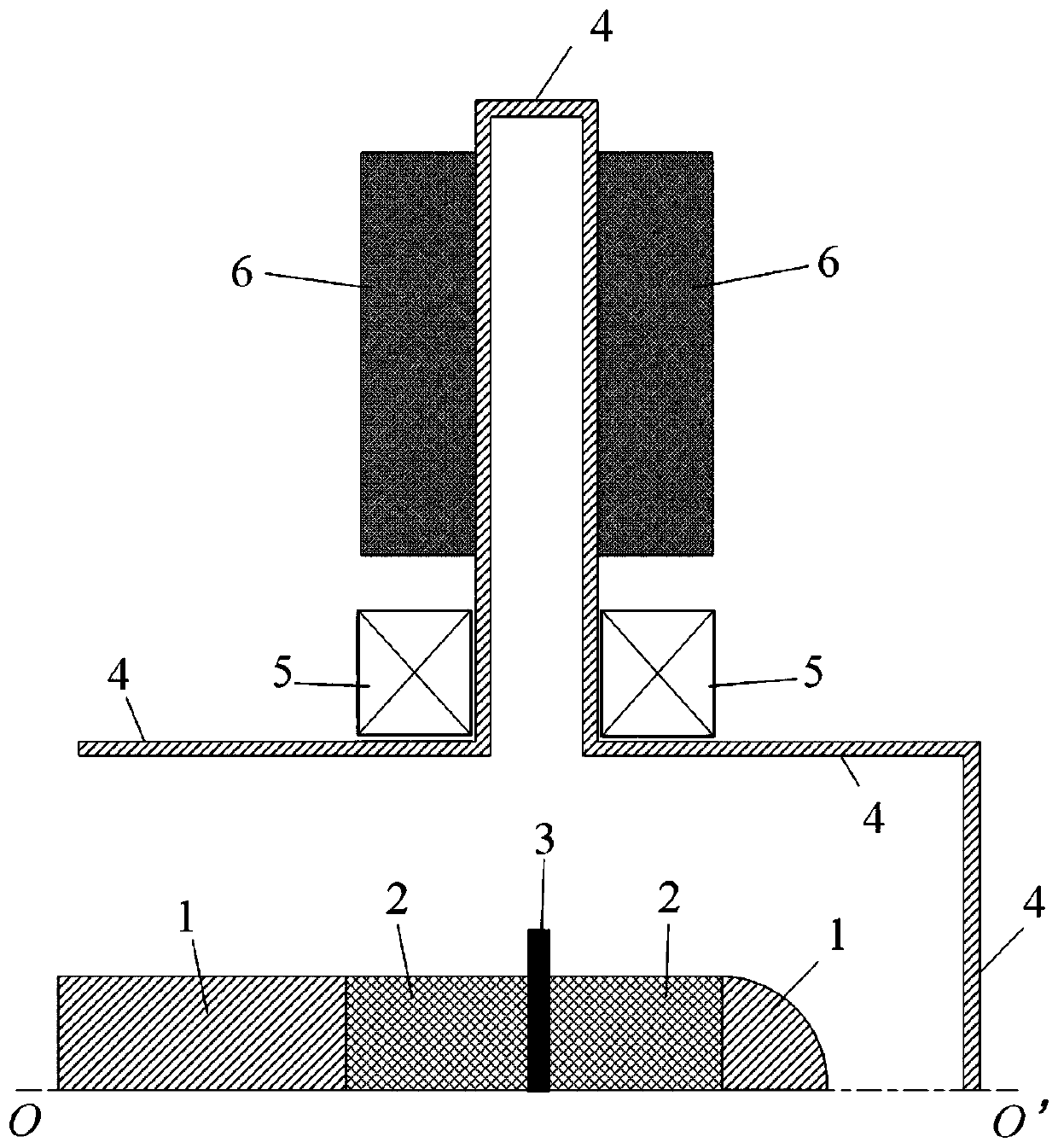
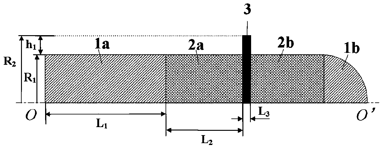
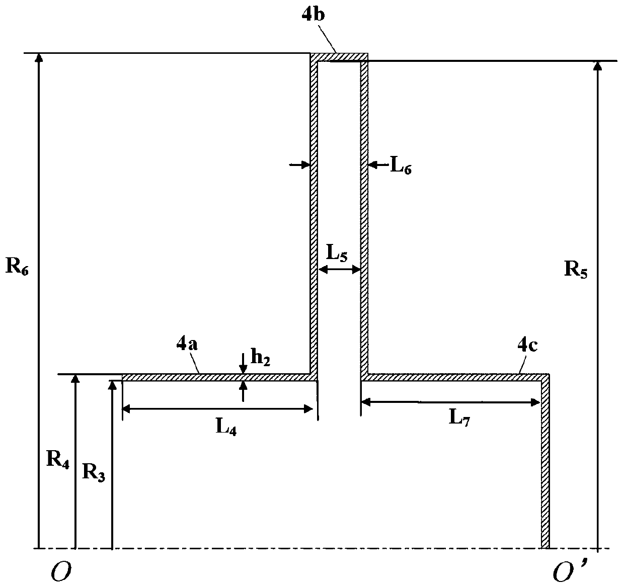
[0029] figure 1 It is an axial half-sectional view of the overall structure of the present invention. Such as figure 1 Shown, the present invention is by diode, 2 solenoid coils 5 (being the first solenoid coil 5a and the second solenoid coil 5b), 2 anode permanent magnets 6 (being the first permanent magnet 6a and the second The permanent magnet 6b) consists of a cathode base 1, two cathode soft magnets 2 (namely the first soft magnet 2a and the second soft magnet 2b), a cathode emitter 3 and a diode anode 4. The left end of the cathode base 1 is connected to the pulse power drive source cathode, the cathode soft magnet 2 is embedded in the cathode base 1 along the axial direction, the cathode emitter 3 is placed in the axial center of the cathode soft magnet 2; the left end of the diode anode 4 is connected to the pulse power The drive sou...


PUM


Abstract

The invention discloses a radial strong current electron beam composite guiding magnetic field system, and aims to solve the problems that a conventional magnetic field guiding system has large weight, high energy consumption and uneven electron beam transmission. The guiding magnetic field system comprises a diode, two solenoid coils and two anode permanent magnets, wherein the diode is composedof a cathode base, two cathode soft magnets, a cathode emitter and a diode anode; the cathode soft magnets are embedded in the cathode base; the cathode emitter is located at the center of the cathodesoft magnets; the cathode base, the cathode soft magnets, and the cathode emitter are coaxially nested in the diode anode; the two solenoid coils wrap the outer surface of a diode anode cylinder; andthe two solenoid coils are sleeved with the two anode permanent magnets respectively; and the two solenoid coils and the two anode permanent magnets are closely attached to the left and right end surfaces of a radial line transmission line respectively; The radial strong current electron beam composite guiding magnetic field system is simple and compact in structure, and can achieve uniform andstable transmission of radial strong current electron beams when small in volume and weight and low in energy consumption.

Description

technical field [0001] The invention relates to a composite guiding magnetic field system in the technical field of high-power microwaves, in particular to a radial high-current electron beam composite guiding magnetic field system composed of soft magnets, solenoid coils and permanent magnets. Background technique [0002] With the development of high-power microwave technology in the direction of high power, high efficiency and miniaturization, high-power microwave devices have achieved fruitful results in terms of output power and work efficiency. As one of the most potential high-power microwave devices, the radial microwave source has the advantages of high power capacity, low beam current density and space charge effect, and can achieve high power and high efficiency under the condition of low guiding magnetic field. Microwave output. At present, radial microwave devices have achieved GW-level output in the Ku-band in experiments. Considering the further practical dev...

Claims


Application Information

Patent Timeline
Patent Type & Authority Applications(China)
IPC IPC(8): H01J29/54
CPCH01J29/54
Inventor 党方超阳福香贺军涛张军葛行军张晓萍袁成卫王海涛
Owner NAT UNIV OF DEFENSE TECH
Why Eureka
Try Eureka